Contributed by Lidio Gentili, IØGEJ |
||
|---|---|---|
| Although these two top-class rigs evolved along very different design paths, and are surely intended for different target markets (look at the price difference!) it is interesting to compare some aspects of the two radios. | ||
 |
 |
|
|
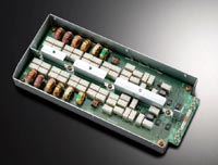
Fig. 1a: IC-7800 Preselector |
Fig. 1b: MkV VRF |
|
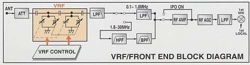
| Preselector Unit: In this unit IC-7800 and FT1000MP MkV are of similar concept; both employ relay rather than diode switching. For trademark reasons, the preselector filter technology is called VRF (Variable RF Front-end Filter) by Yaesu, and DIGI-SEL by Icom. | ||
 |
 |
|
|
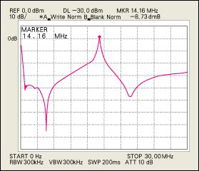
Fig. 2a: IC-7800 Preselector Passband Curve |
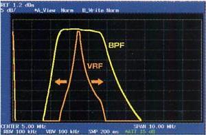
Fig. 2b: MkV VRF and RF BPF Passband Curves |
|
| Preselector Band Pass Diagrams: In Figures 2a and 2b, you can see the effect of the preselector, although the curves are not on the same measurement scale with the currently-available data. (Note that Fig. 2b allows comparison of the VRF and RF BPF passbands.) | ||
 |
 |
|
|
Fig. 3a: IC-7800 RF BPF |
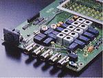
Fig. 3b: MkV RF BPF (centre, inside shield) |
|
| RF Band Pass Filter (BPF): The IC-7800 BPF (Fig. 3a) is located on its own board, and is made up of toroid inductors and silver-mica capacitors with relay switching. The FT-1000MP MkV BPF (Fig. 3b) is in a shielded box located on the front-end board, and is made up of shielded, slug-tuned inductors and and silver-mica capacitors with diode switching. | ||
 |
 |
 |
|
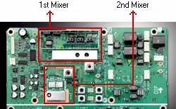
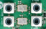
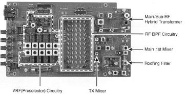
Fig. 4a: IC-7800 1st and 2nd Mixers |
Fig. 4b: Roofing Filters |
Fig. 4c: MkV Front-End Board, showing 1st Mixer |
| 1st Mixer and roofing filter: The IC7800's 1st mixer (Fig. 4a) uses high performance DMOS mixer devices. The FT-1000MP MkV's 1st mixer (Fig. 4c) is designed around four SST310 JFET's. Both have the roofing filter on the same board, but IC-7800 has selectable 6kHz and 15kHz filters (Fig. 4b). In the IC-7800, the 2nd mixer (following the roofing filters) is on the same board as the 1s mixer. The 2nd mixer is an I/Q image-reject down-converter which translates the 64.455MHz 1st IF to the 36kHz final IF in one step. The FT-1000MP MkV's 2nd mixer is located on a different board. Figures 5a and 5b are simplified block diagrams of the IC-7800 and FT-1000MP MkV front ends, respectively. | ||
 |
||
|
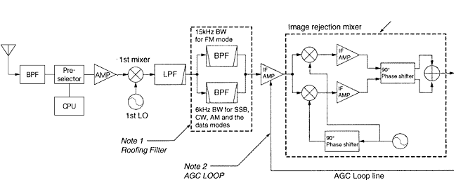
Fig. 5a: Simplified Block Diagram of IC-7800 Front End |
||
 |
||
|
Fig. 5b: Simplified Block Diagram of FT-1000MP MkV VRF and Front End |
||
 |
 |
|
|
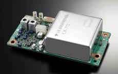
Fig. 6: IC-7800 0.05 ppm OCXO |
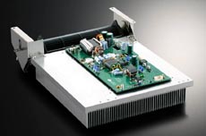
Fig. 7: IC-7800 200W PA and Heatsink |
|
Links: |
||
|
Copyright © L. Gentili 2003 All rights reserved. Last revised: February 27, 2010. |
||
|
This page created by A. Farson VA7OJ/AB4OJ |
||
|
|
||