Start of The TX Board 
1. Use a square to layout the lines on the board, drawing the lines with an extra-fine tip Sharpie pen. For larger projects I use graph paper with 0.25" grid squares. I draw the traces needed on the graph paper first. Then I transfer the grid to a piece of copper board and redraw the traces on the board itself. Even though this process takes some time and concentration, it actually works quite well. I use a fine-tipped, diamond dremel bit to cut the traces on the board itself. This, by far, takes more time than installing the components once the board is constructed.
2. When using a dremel freehand, like I did, layout the circuit one section at a time.
3. After the section has been cut by the dremel, use a hard eraser or Scotch Brite to buff the board, and be sure to blow or brush off the copper grit.
4. Always check each isolated pad for continuity to ground and to other adjacent pads.
5. When cutting more traces after part of the circuit has been built, either use wide freezer tape to cover the components and traces already on the board, or allow some time (overnight?) before cutting more traces. The solder flux residue tends to attract copper grit if it has not had time to harden. (I have not experienced any shorts across the cut traces because of this, but it doesn't hurt to be cautious.)
6. I used 0.20 Kester NoClean solder which worked fine. However, since there is little flux in 0.20 solder, it sometimes is helpful to tin the pad first, using unsoldering braid (wick) to remove the excess solder.
7. I placed the components on the board with a fine-tipped tweezers. This worked fine until the tweezer tips picked up some solder flux, making them sticky. Trying to manipulate a SMT part with sticky tweezers is interesting. About once every 1/2 hour I cleaned the tip of the tweezers with isopropyl alcohol to remove the flux.
8. A neat job can be accomplished by placing connecting wires and jumpers on the bottom of the board. Simply drill a very small hole through the appropriate pads from the top of the board through to the bottom. Be sure to use the dremel to clear the copper around the hole on the bottom of the board to prevent shorting the line to ground.
9. Keeping common components sorted with small Ziploc bags speeds up the construction process. At first I had all my resistors which were still taped together in one large bag. After spending fifteen minutes looking for one resistor value, I decided that it would save time if the common values were sorted and each placed in its own separate bag.
10. When placing an 0603 sized capacitor, don't sneeze. Hi!
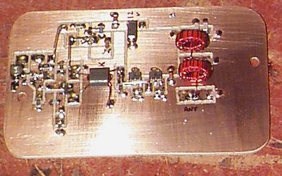
The first project that I built was a 40 meter transceiver. The completed project which includes an SMT Tick 1 Keyer weighs in at a mere 6 oz. The receiver tunes from 7.037 - 7.046 MHz and the VFO capacitor is a polyvaricon. The transmitter functions on two frequencies, 7.039.2 and 7.041.4, and is tuned with a VXO circuit using a 7.040 MHz crystal. A SPDT switch inserts one of two NPO capacitors into the circuit to select the transmit frequency. The transmitter provides 1W of output. Here are some photos of the SMT-40 Ultralite. Unfortunately, I forgot to take a photo of the transmitter after it was finished and it is now buried beneath the receiver. The receiver has a 6-pole crystal filter; five crystals are mounted on the bottom of the board and one crystal is visible on the top of the board (I ran out of room, Hi!). I plan to use this rig on backpacking trips and possibly in the Spartan Sprints.
Start of The TX Board

Completed Rig 
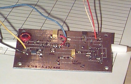
This rig was created with a special purpose in mind. Several of my ham friends and I chat in a small 75 meter net on Monday nights. I wanted a rig that I could use to listen to the net while backpacking or camping, and I wanted to be able to check in using CW. I also wanted to be able to move down to the CW portion of 80 meters. Thus, the VFO has a switch that toggles in fixed capacitors to move to the lower part of 75 meters or the 80 meter CW sub-band. The transmitter output is about 2.5 watts on 75 meters and 2 watts on 80 meters. The VFO is varactor tuned with a ten-turn pot. Filtering is provided by a 4 pole crystal filter with a bandwidth of 2.5kHz (SSB) and there is a 700 hertz passive audio filter that I can switch in for CW. This was a fun project. The most challenging part was building a good receive bandpass filter that was wide enough to cover this much of the spectrum without too much loss.
Front View 
Receiver 
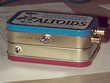
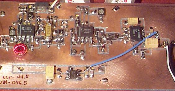
Top View 
This is an effort in minimalist, lightweight design. The largest component is the Radio Shack audio transformer. I sized the boards to fit into Altoids boxes. The double-tuned RX bandpass filter works well at keeping out strong shortwave signals. The transmitter is a slightly modified Micro-mountaineer circuit. Output is 700mW. Bottom Photo: The RX is housed in the red Altoids box and the TX is housed in the blue box. T/R switch and earphone jacks are on the front side while the ANT, 12V and KEY jacks are on the end. The box is designed to stand on end with the T/R switch side facing up (for convenience in a sleeping bag or tent.) The entire transceiver weighs in at 5 oz.!