One of the goals for this project was to use components that I already had in my junk box. Thus, the frequencies of the IF/BFO and VFO reflect what I had in my "crystal bowl," as AA3PX calls his crystal stash. The S7C RX circuit is suitable to a wide range of adaptation. So don't be afraid to experiment with what you have on hand.
The S7C Receiver is described in Experimental Methods in RF Design by Hayward, Campbell, and Larken, published by the ARRL in 2003, and is found on page 12.16. The S7C is a superhet which uses discrete components that are easily obtainable. It does not, however, sacrifice performance by its simplicity. Quoting from EMRFD, "This mixer has some strong virtues. First, it is quiet: We measured a 10-dB noise figure with this circuit. The current is low at about 3mA. Very little LO power is required. . . . We measured IIP3 of +5 dBm for this mixer, making it suitable for wide dynamic range applications. . . . The receiver is a joy to use. The first experiment that is always performed with a new receiver is a session of listening. The narrow bandwidth is effective on a moderately crowded band, yet the use of just two crystals produces a bright and lively sound not compromised by excess filtering. . . . We measured MDS of -138 dBm with this receiver, consistent with the NF measurement and overall bandwidth slightly narrower than the 500 Hz of the crystal filter."
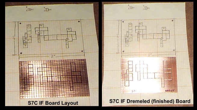
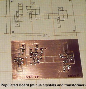
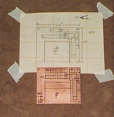
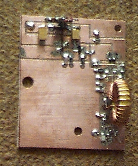
Below are two photos of the initial stages of construction, using grid paper (1/10" spacing), a pencil, and an extra fine Sharpie pen. The photo on the left shows the 2" x 3" board on which a grid of the exact spacing has been drawn, and the circuit pads transferred from the paper drawing to the grid on the board. The second photo shows the board after the pads have been created by the dremel.
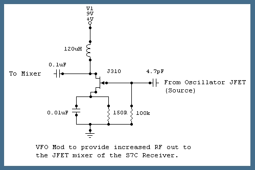
The completed VFO is displayed below. The board itself was not very complicated; however, I spent a considerable amount of time troubleshooting the circuit after it refused to oscillate. The culprit component was a shorted capacitor (not across any of the dremeled lines, but within the component itself). The board was also trimmed to fit a different enclosure than first anticipated. I also modified the VFO circuit to provide an increased RF voltage to the mixer. It worked as published but the increased VFO signal provided stronger, cleaner reception. The schematic of the mod is included here in case you are duplicating this project. (Mike, W3TS, suggested I try this mod.)
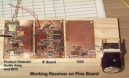
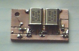
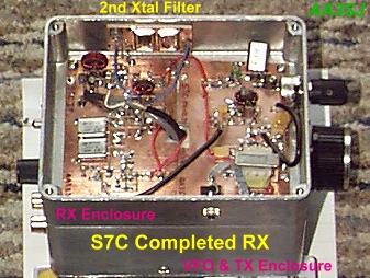
After testing the receiver, confirming its operation and listening to it on the air on several nights, I then moved the IF to 8 MHz and the VFO to 6.160-6.200 MHz. The VFO can be fine-tuned by adjusting the turns on the toroid inductor; It can be moved about 70 kHz in either direction in this manner. After listening to the RX I decided that I wanted to include additional Xtal filtering (another 2-Pole filter inserted into the IF as Hayward suggested in EMRFD). This additional filter (shown in the photo below on the left) drastically improved selectivity. As can be seen in the photo, the capacitors are SMT. This filter was then bolted to the side of the enclosure and can be seen installed in the photo on the right. The VFO is housed in the dicast enclosure on the bottom of the photo and the RX is housed in the smaller dicast enclosure on the top. This enclosure scheme works very well and involves excellent shielding. The design is similar to the "Sleeping Bag Radio" also described in chapter 12 of EMRFD.
ADDENDUM
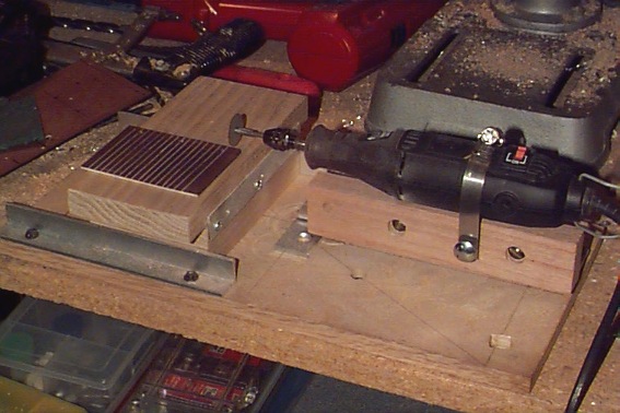
Wes Hayward, W7ZOI, has designed and built an X-Y table jig to use a Dremel with a cutting wheel to make breadboards that work with SMT components. The photo below is my version of W7ZOI's X-Y table. I'm still experimenting with this technique, but it does have some advantages over my "freehand" technique just described. Here's a link to Hayward's page: W7ZOI SMT Breadboarding Experiments.