 ZS6DX/V51VE
ZS6DX/V51VE
Building the Softrock
Ensemble II SDR Reciever
A while ago I imported a Softrock Ensemble II SDR receiver kit. The
plan was to build the kit and use it as a pan-adaptor connected to the IF
output of my Yaesu FTdx-5000MP. Once I started using the FTdx-5000MP I
realized that the standard band scope is more than good enough for what I
want.
So the kit sat on the shelf for a while. I also recently
bought the Softrock SDR transceiver kit. I am quite keen to get this kit
running as it would be the ideal QRP SDR that I can run remotely. After
looking at the kit and all the tiny surface mount components (SMD) it
contains I decided to build the receiver first as an exercise. The
receiver's construction is similar to the transceiver but there is just
less.
Below I have documented the build process, broken up in
sessions as I found time to build.
Just a bit of background on my
electronics and kit building experience.
I started my work life as
a computer engineer fixing mostly mainframes down to component level. This
was fun and I learned to solder and use instruments like DVM's and
oscilloscopes. But this was a long time ago, from around 1984 to 1987.
This was all before surface mount components or large scale integration
chips (LSI). Since then I did build a few smaller kits, general things
like battery chargers and a few ham kits but nothing major and again no
surface mount components. I also spent many hours fixing and modifying
amateur radio equipment.
SO as far as building is concerned my main
concern was the surface mount components, and some of the are TINY! The
3.3V regulator is around 2mm long....

The Ensemble II
kit as unpacked, with my little helper.
The first task was to ensure all the components are there, this
checked out well with only one thing that confused me. According to the
list of materials the kit is supposed to contain #30 magnet wire to wind
the inductors. My kit contained 2 rolls of wire but they are not the same!
They are very close so it is difficult to judge which one is 30 gauge.
Time will tell.
The first step is to build the 12V power supply.
This supply provides 12V and 3.3V to the rest of the PCB. This stage also
contains the smallest surface mount component the 3.3V regulator so I knew
this would be the acid test, if I could not get this right I might just as
well dump the 2 Softrock kits!

Components of top
of the PCB for the voltage regulator, easy to build.
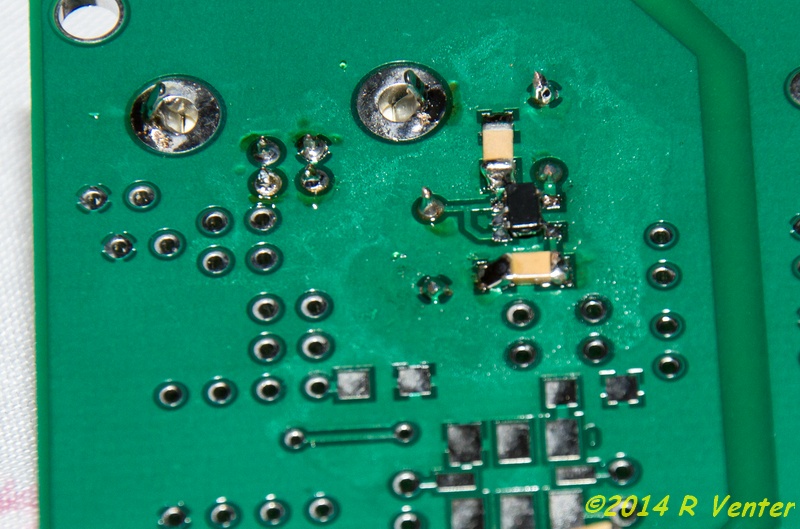
The surface mount
components at the bottom, see the tiny black voltage regulator.
As it turned out I did manage to get this bit built and it actually
worked! Now I knew I had a chance of completing the project!
Next
came the USB power supply, this is the 5V supply derived from the USB port
on the computer and it is used to run things like the local oscillator
(LO). It again contained a few surface mount components but nothing
difficult.
Now the fun starts! The LO is next and it includes the
SiLabs Si570 programmable oscillator, another tiny surface mount component
that only has solder pads, no pins. Fortunately I manage to get this stage
completed as well. I found that you need good light, patience, a steady
hand and lots of liquid flux!
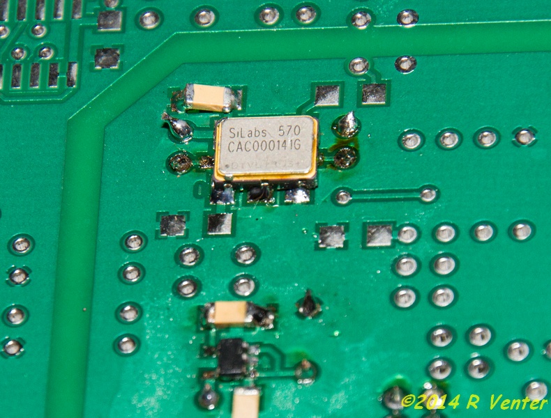
The little Si570
programmable oscillator.
During the construction of the LO I also had to wind the first inductor. I found the instructions on how to do this less than clear, not so much how to wind it but how to install it, they do not really show what side of the transformer goes where. I spent some time studying the schematic and comparing it to the PCB and the went ahead and installed it the way I thought is should be. Turned out I did get it right!
The transformer
as installed.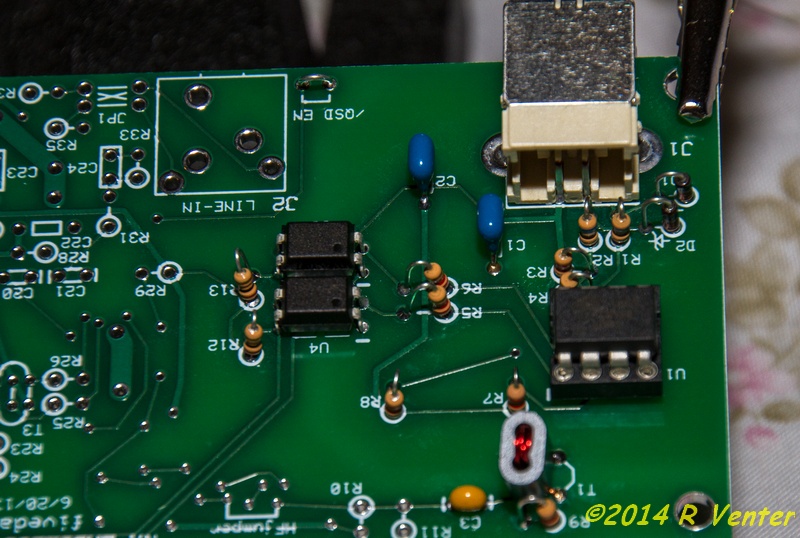
The completed local oscillator section.
To test the LO stage you have to install some software, first the USB
driver for the SDR and the the programming software for the Si570 chip. I
also installed SDR# software to check is the LO was functional, you can
already change frequency at this stage.
Below you can see the
software that programs the Si570 running, it passed all tests.
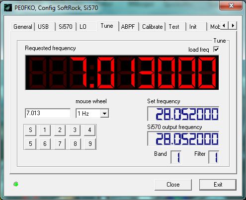
Checking the agility of
the Si570
I also ran SDR# software to see if it would see the LO and specifically the Si570, no problems were encountered!
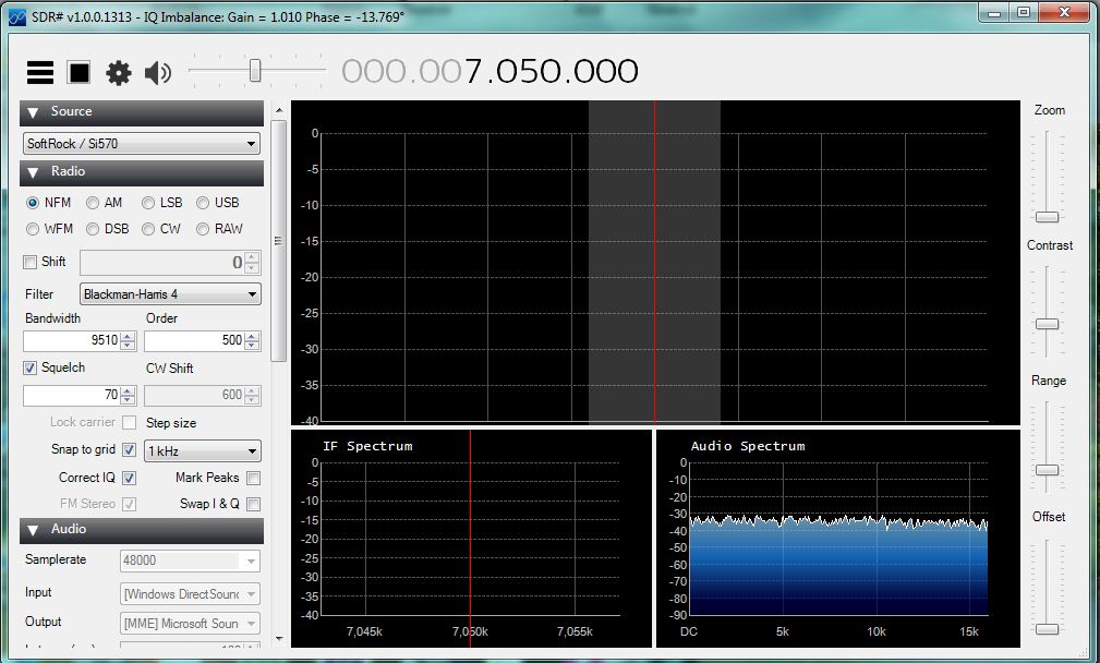
SDR# running on the
Si570 in the LO of the Ensemble II
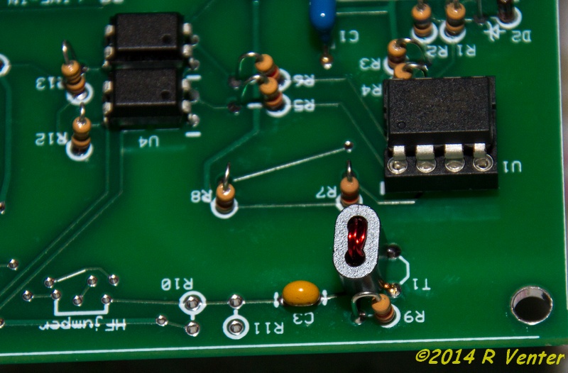
All went well and the PCB passed all tests up to this point!

This is how the
PCB looks at this stage, lots more to do!
At this stage I had spent 4.5 hours on the project and since the bands
were open I decided to call it a day, will continue tomorrow, time to DX!
(c)R Venter 2014