Using the Heath SB 220 Linear on 50 and 70 MHz
ZS6BTE, reprinted July 2015 to incorporate 70 MHz usage
|
Make sure the warnings in the tune up
procedure concerning the HV lines are understood before doing anything! |
The SB220 is a HF SSB amp using Eimac 3500-Z tubes and is capable of about 1.5 kW PEP output on 7 MHz. To anyone versed in VHF construction techniques it is immediately obvious the spindly VHF-unfriendly tubes and layout within the amp enclosure will result in poor input-output isolation. Also the T/R switching relay is not truly suitable for VHF use. However, since all is available in a single enclosure for use, modification has the attraction of convenience.
This is an easy mod providing 10x gain on 4m and 5.6x gain on 6m (10x on 6m if set up for use only on 6m) and it provides enough power for most requirements on the band.
So around 1kW PEP output can be obtained, but see notes regarding output inductor compromise in dual band operation.
Two of the band switch input positions need to be sacrificed – I used the 10m position for 6m and the 15m position for 4m.
Ideally the band switch needs to discarded for VHF use, but in this application has to be retained for input switching between 6 and 4m.
However, on the output side the band switch is left unconnected (otherwise it will burn due to the high SWR caused by its HF only construction) and the anode line passes straight through the chassis hole to the connection point.
The inductance of the 10 and 15m input coil formers needs to be reduced, while using 20 pF capacitors across each side as necessary.
All the output HF connections remaining were clipped off and discarded to prevent stay resonances.
Modification details:
Remove the
mains power input at the wall.
Input circuit
Remove the covers and the front panel. The two dial switches do not need to be loosened – their wires are long enough to swing the front panel to one side.
While busy here, install back-to-back 1N4007 diodes across the two wires feeding each meter on the front panel. This protects the irreplaceable meters from destruction should there be a glitch at any time.
Remove the 10m-coil former and remove half the turns, spread the remaining turns a bit. Make a simple tool (3mm braising rod bent 110 deg and the bend cut 5mm long to form a hook) to unclip the former.
Use 20 pF mica capacitors each side of the coil, start with about 40 x 40 pF. If the circuit does not have enough tuning range at 50 MHz remove another turn or two.
I ended up with about 80 x 80 pF of capacitance across each side of the coil, but the exact value depends on the characteristics of the cable or circuits between the amp and driver rig.
Do the same to the 15m input circuit - I used 80pF plastic foil trimmer caps instead of fixed ceramic disk caps because only 35W of drive was available on 4m.
Set up for minimum SWR as seen at the rig (ATU must be off).
Anode blocking capacitor
The standard 1000pF green polyester capacitor can be retained, at the expense of 10% of the output power. Rather replace it with a UHF quality high voltage capacitor of at least 150 pF or so. A single 51 pF cap proved too small and caused instability in the amp. I used two caps in parallel totalling about 180 pF.
Suppressors
The standard suppressions, or replacements, HAVE to be retained otherwise the plate current is pinned at full scale immediately TX is switched (even without any drive!) and the 3-500Zs would be destroyed very quickly.
My suppressors had to be replaced and I could not obtain replacement 5W 47 ohm carbon composition resistors so I used 2 turns of 1mm copper wire wound around a 3W 47 ohm carbon film resistor. The wire must not touch the body of the resistor. This is the lower limit acceptable and the amp must be tuned up initially using minimum power otherwise the resistor burns due to the high initial output SWR until tuned up, especially on 4m. Metal film resistors should not be used due to their high-inductance helically-wound construction.
A high SWR on the antenna is guaranteed to burn the suppressors, particularly on the tube with the higher gain, so make sure the antenna's SWR is around 1.4 or less.
LOAD capacitor
This is used in standard form, untouched.
TUNE capacitor
This was disassembled to reduce the number of vanes to 4, then reassembled in that format. This reduces the minimum capacitance of the TUNE cap making it still useful on 70 MHz, but only just.
High voltage choke
To be on the safe side 2/3 of the turns were removed, although it was used standard when the amp was used initially only on 6m.
Grids
The existing caps and inductors on all four grid pins should be removed and replaced with copper straps, shortest route to nearest ground.
Output circuit
An indirect problem is excessive capacitance due to layout in the standard enclosure.
For dual 6 and 4m use I used straight 3mm copper pipe connected between the tuning cap and the output connection point, by-passing the output side of the band switch. This is suitable for 10x gain on 4m, but is not optimum for 6m operation . Any additional inductance on this line severely reduces the 4m output power.
For 6m only around 1 and a half loose turns are required, under experimentation, to get 10x gain. See illustration below.
Pay attention to keeping the route away from the casing to prevent capacitance effects loading up this new line.
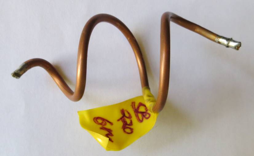
Output inductor for 6m only use. For both 6 and 4m use this is not
coiled.
Tune up procedure
This is hazardous!
Before switching on the rig:
Identify the HT override flap in the RF output compartment, which shorts out the HT when the cover is removed.
Identify the very hazardous HT post feeding the HT from the power supply through the input circuit enclosure to the RF output compartment.
Jam a many folded paper sheet between the HT override flap and the shorting post to override this safety feature.
Insulate the front panel hanging on its wires.
Connect amp to antenna circuit, and to the driver rig – incorporate all local cables, preamps and power meters, etc., that will be used.
Switch on the amp.
Switch on the driver rig.
If the driver rig has an ATU, turn it off.
Reduce output power on the driver rig to minimum.
The procedure now is to key the driver rig in a mode such as RTTY, FM, AM, etc, while twiddling the slug in the 10m input coil with a plastic tool for minimum SWR on the driver rig, tweaking the amp’s tuning and loading caps for maximum output from the amp, while keeping away from contact with that HV post in the input circuit enclosure.
If all seems OK so far, increase power drive (use a pulser such as fast CW dots to reduce dissipation in the amp) and repeat the process.
If the SWR at the driver rig is still too high, possibly more capacitance and less inductance is required at the input circuit.
Do the same on the 4m line.
Results
Note the SB 220 is a CW or SSB amp and at higher power output one should bear in mind that a typical SSB transmission has a 25 % duty cycle.
I do not know what the harmonic content of the output circuit is, particularly at 100.2 and 150.3 MHz if one uses 50.11 MHz a lot, but see the interference investigation results below.
See the Table below for typical output power as measured on this amp, as set up for dual 6m/4m use.
If a good amp cannot deliver similar to this with 100 Watts of drive, the problem is almost certain to be excessive capacitance on the plate circuit. Re-investigate the mod and use even wider copper tape to reduce the inductance as far as possible, and make sure the route is not too close to any casing.
I have used this amp freely on WSJT FSK441 and ISCAT-B modes on both 4 and 6m at full power available without problems.
Remarks arising
With the compromised anode inductor the 6m efficiency is rather low with high plate current, but efficiency is better on 4m. Note the output gain slope across the 4m band indicating the amp is being used at its upper frequency limit..
When using this amp (or any other amp for that matter)
driven by one of the 13v solid state exciters (IC 706, 746, 756, various
Kenwood and Yaesu rigs) the poor TX IMD generated by
these rigs causes immense problems for other users on
the band as the amp amplifies these IMD products. Therefore the audio drive
should be kept to minimum to achieve the required power output and in
particular the ALC indication on the driver rig should just about never be
visible.
External ALC between the amp’s ALC input and the ALC output of the driver rig should not be used, it is too slow and will still allow splattering – make sure the audio drive at the driver rig is correct instead.
Note that the SB220 is unsuitable for VOX use or direct CW as the T/R relay is too slow. For CW first place the rig in TX to switch the SB220, then send CW. With WSJT digital modes using a hard wired PTT line (do not use VOX!) there is a suitable audio delay on SSB before drive is applied to the SB220, so there is no possibility of hot switching the amp and damaging the T/R relay - make sure the mic is not live or pull it out.
Ensure the rigs PTT current handling is sufficient to drive the T/R switch on the SB220, otherwise the rig may be damaged.
Table of Results in dual band operation
SB220 50 MHz tune up results with IC-746
driver rig
RTTY mode, SSB voltage on SB 220, with dual VHF yagi
30 May 2012
|
Freq |
Drive power |
Power PEP |
Gain dB |
Power EIRP, ant 12 dBi |
Plate Amps |
Grid mA |
|
50.115 |
95 |
500 |
7.2 |
8109 39 dBW |
.7 |
140 |
|
50.200 |
95 |
500 |
7.2 |
8109 39 dBW |
.7 |
140 |
|
50.250 |
95 |
500 |
7.2 |
8109 39 dBW |
|
|
SB220 70 MHz tune up results - RTTY mode, SSB voltage with dual VHF yagi
Driven by 70 MHz Spectrum Communications transverter TRC4-10sL
|
Freq |
Drive power |
Power PEP |
Gain dB |
Power EIRP, ant 13.4-14.1 dBi |
Plate Amps |
Grid mA |
|
70.000 |
33 |
375 |
10.5 |
8395 39.2 dBW |
.49 |
|
|
70.050 |
34 |
350 |
10.1 |
8018 39.0 dBW |
.49 |
|
|
70.100 |
34 |
315 |
9.6 |
7384 38.7 dBW |
.49 |
|
|
70.150 |
35 |
290 |
9.1 |
6956 38.4 dBW |
.49 |
|
|
70.200 |
37 |
280 |
8.7 |
6873 38.4 dBW |
.49 |
90 |
|
70.250 |
37 |
250 |
8.2 |
6279 38.0 dBW |
.5 |
|
|
70.300 |
37 |
220 |
7.7 |
5654 37.5 dBW |
|
|
PS - Interference Investigation was Passed
Following complaints from neighbours concerning TVI, my station was formally investigated by the local TVI investigations authority.
The linear at the time operating only on 6m combined with two 50 MHz yagis, was found to have harmonics below –60 dB EIRP when running 400 W, the maximum permissible in ZS at the time. The official mentioned that in South Africa’s TV bands (Band 3 VHF and Bands 4-5 UHF), he was not able to detect any harmonics/spurious signals strong enough to interfere with local TV channels on the measurement equipment used. Nor harmonics interfering with local FM radio channels.
This echoes the results seen on my own TV reception when running this linear.
The station was thus given a written clean bill of health as my other equipment was examined at the same time.
The neighbour’s problem was found to be badly made off coax around a DVD, satellite RX, VCR, distribution amplifier, and the TV. Somehow he had contrived to arrange 115 volts (half mains voltage) on these cables, so his “complaint” might have saved his life!