LNB Test Results
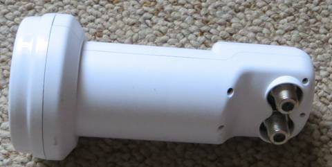
Octagon OTLSO Twin LNB Slim OPTIMA
Using a Ku band satellite TV LNB on the 3cm amateur band (tested 17 Jan 2016 )
ZS6BTE January 2016
Commercially available Ku band LNB's offer many advantages for radio amateurs, these include a built-in feed horn, state-of-the-art low noise transistors, crystal-PLL LO, RF mixer to a suitable IF, IF amplification, high gain, voltage regulation, water-proof housing, built-in IF output connectors and cheap price.
When I used an old style LNB with wave guide input to monitor the November 1997 ARRL EME contest traffic on 3 cm (10368 MHz) I had to make a wave guide transition to a home-brew scalar ring feed horn for the dish, and all the parts mentioned above other than the low noise input stage of the LNB which I still had to modify to get the NF down to around 0.6 dB or so. The rest of the LNB I could not use. That system, when installed on a 3m home-brew dish, produced up to 2.5 dB of moon noise and the system performance was good enough for monitoring the EME traffic.
Lately, LNB's incorporating a PLL LO have become available and I was keen to test such a device as a possible front-end for receiving the amateur transponders around 10490 MHz on the Es'hail 2 satellite due to launch later this year, while using a USB dongle around 740 MHz as an IF receiver.
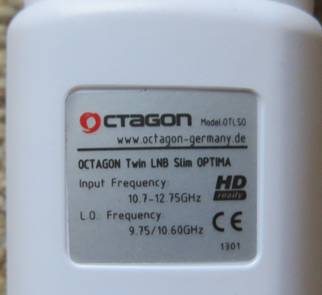
Label photo
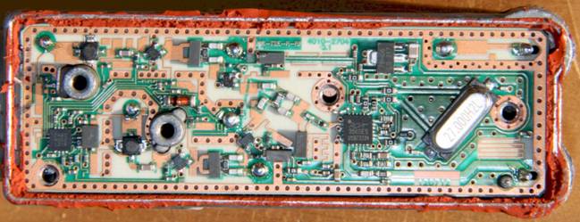
Internal view of OTLSO (photo: David, G0MRF)
Description
As can be seen from the label photo above, the device in not made in Germany and identical hardware appears in other countries under various trade names. It is probably made in China for various re-sellers, world-wide.
This is a modern Ku band LNB using the latest low noise RF transistors, and ICs to control d.c. bias for the RF front end and generation of the LO carrier frequency by phase-locking the 27 MHz crystal oscillator to an internal reference. The 27 MHz is multiplied by 361.111 to get to the default LO frequency of 9750 MHz which is used in amateur 3 cm operation (10368-9750 = IF of 618 MHz, etc), when 12V is applied at either of two "F" connector outputs. The IF appears on both outputs.
Each RF input from a linear probe in the circular waveguide (horizontal/vertical) has three RF stages, so at least 36 dB of the claimed 60-65 dB gain is at RF, the rest is in the PLL/IF amp chip. A 6v regulator supplies the various devices.
The LNB has a circular feed horn to match the typical f/D of around 0.7 used in standard offset feed Ku band TV satellite reception dishes. Polarisation is set up according to voltage input (12v or 18v) as either vertical (default 12v) or horizontal 18v.
The switchable 10.6 GHz LO is probably of no further interest in amateur operation at X-band.
RF front end devices
The Octagon LNB literature (and various other trade marks) throughout the internet claims a NF of 0.1 dB. This is impossible - the LNB noise figure cannot be better than the 1st RF amplifier.
Typically, the input circuit introduces losses degrading the NF by a further 0.2-0.3 dB, so around 0.6 dB NF in-circuit is the best to expect at Ku band and maybe 0.5 or so at X band (when the circuit is set up for X band).
The first RF amplifier is probably the NE3210, the best device in the NEC catalogue, or similar from other manufacturers.
NE3210: NF = 0.35 dB TYP. Ga = 13.5 dB TYP. at f = 12 GHz
This device is unconditionally stable (Rollerts stability constant K>1.0) above 8500 MHz.
The next two devices are the NE3503, labelled "V75".
NE3503: NF = 0.45 dB TYP., Ga = 12.0 dB TYP. at f = 12 GHz
This device is probably unconditionally stable (Rollerts stability constant K>1.0) above 8500 MHz, having less gain and therefore less inclination to oscillate.
Functions of the RDA3560 PLL chip (copied from data sheet)
· CMOS Integrated Ku band to L band downconverter
· Integrated VCO and PLL
· Integrated pre-amplifier, mixer and L band buffer amplifier
· Integrated reference oscillator ( 27MHz is default )
· Integrated 22K tone detection and polar voltage selection
· Integrated negative voltage generator and phemt FET bias control
· Low phase noise
· Switched LO frequency between 9.75GHz and 10.6GHz
· Also support 10.75GHz LO frequency
· 4.5V to 5.5V operation
· Low spurious
Note that the chip is running off the 6v regulator on the PCB, which exceeds its rated voltage.
Test Results
Frequency stability
The 27 MHz LO crystal is a cheapie and accordingly drifts during warm-up. For the first 20 minutes the LNB is quite useless for narrow band working. After 40-45 minutes (tested indoors), the LO frequency stabilised to 1 Hz at 27 MHz per 5 minutes or 360 Hz per 5 minutes at RF (9750 MHz). The LO at 9750 MHz ended up 36 kHz low, and reset to this same value subsequently (again indoors) when restarted. Once warmed up after 45 minutes it is thus very suitable for narrow-band working, provided time periods are not more than a minute or two.
There are mods available, including injection-locking the 27 MHz crystal to a GPS PLL oscillator, or directly replacing the crystal with a TCXO (David, G0MRF in "Oscar News" 211 Sept 2015).
Noise performance
I used the sky-ground Y-factor method to establish the noise figure and examine the performance slope across some of the amateur 3cm band 10368-10490 MHz (latter freq proposed for the Es’hail-2 satellite due for launch this year).
|
IF freq |
Y-factordB |
Tsys k |
NFsys dB |
GaindB relative to IF 1200 MHz |
Remarks |
|
600 |
nearly dead |
|
|
-30 |
10350 MHz |
|
618 |
1.5 |
480 |
4.2 |
-24 |
10368 MHz |
|
700 |
2.6 |
206 |
2.3 |
-10.3 |
10450 MHz |
|
740 |
2.8 |
180 |
2.1 |
-9 |
10490 MHz |
|
800 |
3 |
158 |
1.9 |
0 |
10550 MHz |
|
900 |
4.5 |
55 |
0.7 |
0 |
10650 MHz |
|
1200 |
4.8 |
42 |
0.6 |
0 |
10950 MHz |
|
Tsys = [(T 0 - Y.T cold )/(Y-1)]
NFsys dB = (Tsys /297 + 1) 10log10
RF = IF freq + 9750 MHz
Conditions: Ground/cold sky method used to obtain Y-factor Ambient temp 297k (24°C) Sky background - clear in target area Antenna temp - taken as 70k, also best fit to expected result at 1200 MHz IF Attenuator - Weinschel 9621 precision 1 dB steps monitored on Rx d.c. AGC output Supply voltage - 12V from Thomson FTA sat receiver, LNB loop through used as IF, LO freq ~9.750 GHz Rx - ICOM IC-R8500 in wide band 12 kHz AM mode This LNB has a PLL 27 MHz crystal controlled LO |
|||||
Table 1 - Sensitivity test results
Interpretation of noise performance
Caveat: There is some possibility the integrated feed horn is not optimised for the commercial TV offset sat dish I used. If the dish were over-illuminated the pick-up would reduce the hot/cold Y-factor ratio and make the LNB appear less sensitive, but the results are as expected and indicate a good feed horn to dish match..
As is the LNB is too noisy for EME at 10368 MHz. Some patching on the input transistors is required to get the NF down to the potential 0.5 dB.
For the Es'hail 2 satellite, patching the front end to get a NF of 0.5 will increase the return S+N/N ratio by 3.4 dB from 13 to 16.4 dB for a 0.6m dish, or else a user may double the diameter of the dish to 1.2m to achieve the same result.
The LNB's sensitivity is OK for local use such as beacon reception, ATV or rain scatter QSOs on 10386 MHz, but on a standard LNB there is every reason to use the upper part of the 3cm band around 10.5 GHz as seen in Table 1 if sensitivity is important.
Further information
Log into the WebSDR at http://websdr.suws.org.uk/ and select 3cm to gauge the on-air system performance when using this LNB as a receiver of the GB3SEE 3cm beacon.
For further technical information on dozens of LNB's of this generic type log in to alibaba.com and do a search for "Ku band PLL LNB".