High Performance Three Element Yagi for 40.680 MHz
©ZS6BTE
ZS-amateurs have been able to work a sliver of
bandwidth between 40.675 and 40.685 MHz (i.e. 10 kHz) as a primary use
allocation for "Propagation studies only" for several years, but
contacts and reports are non-existent at the time of writing. This is the sole
allocation in the world and the band is believed to have special properties,
being halfway between the 10m and the 6m bands, and reportedly from military
use, has enhanced meteor scatter reflections at the wavelength, also low VHF
propagation characteristics not available anywhere else in the amateur
frequency spectrum.
The allowance is generous in
terms of the conditions: power limit of 26 dBW (398
W) PEP output, in any mode except pulse and fast scan television. Strangely,
there is a note
that "Satellite" is "Allocated" whatever that means.
In recent months, and under
weak propagation conditions, the OZ7IGY beacon (10W ERP, omni antenna) on
40.021 MHz was received a few times by me in Johannesburg KG33xv.
The other beacon in the band,
GB3RAL on 40.050, was not heard and apparently was just recently returned to
service according to a VHF DXer in
These two beacons should be
monitored around the TEP season starting in early September.
An immediate obstacle is the
lack of commercially available equipment and this has put a brake on possible
activity: this article goes some way in addressing this problem.
The ICOM IC-746
transceiver and variants can be modded to provide full performance on the band,
and without investigating further, I would guess also the IC- 756 and variants.
If interested, ask me for details of this mod.
Three Element Yagi Antenna
This antenna was designed to
provide good gain with very good rear-and-side lobe performance to suppress
unwanted pick-up; a preliminary investigation had revealed in-band QRM from
various sources. All parameters were optimised in NEC prior to constructing the
antenna. Particularly, the antenna takes a direct match to 50 ohm coax without
matching hardware being required, thereby reducing losses.
The antenna has a reflector,
director and folded dipole driven element, with all elements grounded to the
boom. It is actually intended for use on 40, 50 and 70 MHz by unscrewing and
relocating the various elements to marked positions and lengths to suite these
frequencies in the mobile environment, this does not take long, but is not
detailed here.
Since an antenna for this
band is not commercially available, a number of illustrations are provided to
assist those constructing their own.
Table 1: Summary of performance as modelled
|
40.680
MHz band |
|
|||||
|
MHz |
Gain, dBi |
Fr/back ratio, dB |
Fr/rear ratio, dB |
SWR 50 ohms predicted |
SWR 50
ohms measured |
|
|
40.0 |
7.9 |
12.4 |
12.4 |
4.4 |
>3.0 |
|
|
40.680 |
8.2 |
29.6 |
28.1 (11.3 vert plane) |
1.2 |
1.1 * |
|
|
41.0 |
8.3 |
19.9 |
11.8 |
1.6 |
1.1 |
|
* driven elements tuned to minimum
SWR by length adjustment
NEC Pattern and Sweep Simulations
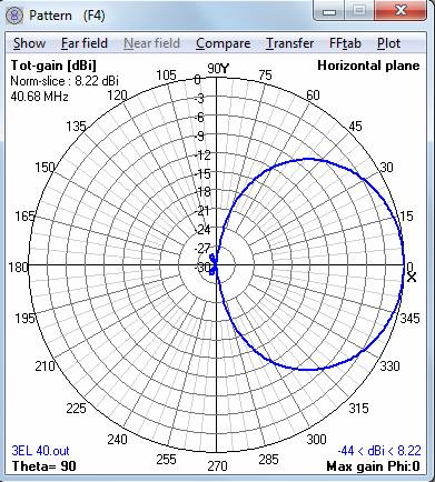
Horizontal pattern at band centre
40.680 MHz
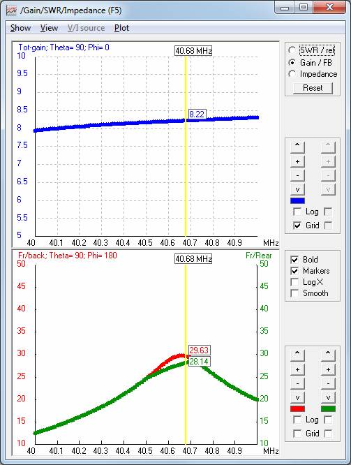
Gain and lobe sweep
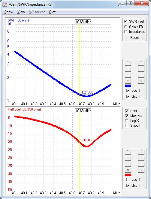
SWR and return loss sweep
Construction
details
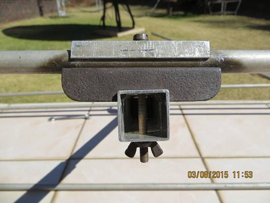
Mounting the director and
reflector elements on the square boom

The feed point is on the top
dipole insulated from the boom with a piece of wood. The bottom dipole is
grounded to the boom.
The whole assembly is kept in
place with the bolt passing down from the top to the nut on the bottom
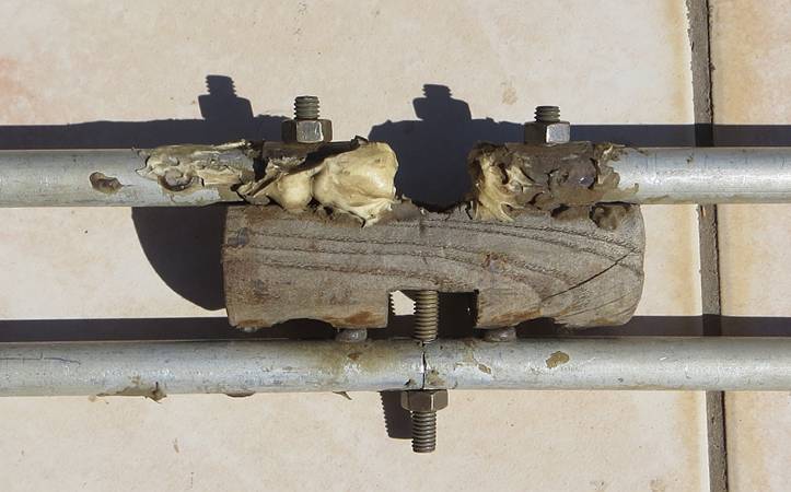
Side view of the feed point with
the square boom passing through the wood insulator removed
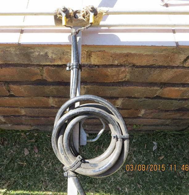
Current balun
at the feed.
The u-clamp under the balun mounts the antenna to a vertical mast boom
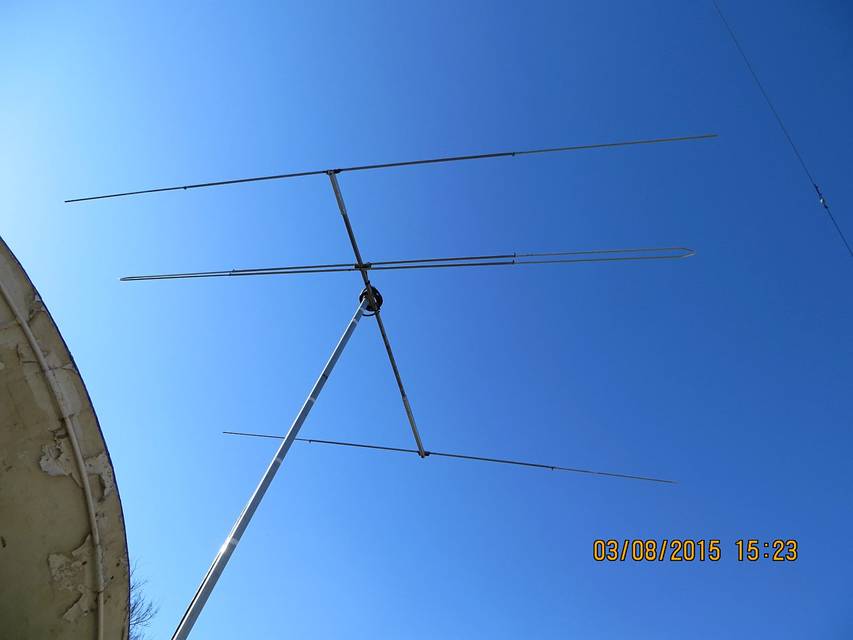
Overall view of antenna as mounted.
Note the telescoping outer pieces with clamps on all three elements
Dimensions
Corrected
for the boom shortening effect of 66% of boom diameter
|
Overall
length of reflector |
3.672m |
|
Dipole
spacing from reflector |
0.572m |
|
Overall
length of dipole |
3.488m *tune length for best SWR, corrected here |
|
Overall
length of director |
3.276m |
|
Director
spacing from reflector |
2.065m |
NEC file
CM file "3el 40.68MHz Yagi.nec", optimised result
CM NEC Input File
CM Elements 12 mm hard
aluminium round tube grounded to the square boom which is 25mm hard aluminium.
CM Telescoping
elements 10mm commercial aluminium round tube
CM Direct 50 ohm
feed to folded dipole driven element
CM Dipole separation
50mm, grounded to boom opposite feed point
CM Gain 8.2 dBi and
f/b 29.6 dB, f/r 28.1 dB (horiz plane), f/r 11.3 dB (vert plane)
CM No correction for
the telescoping sections diameter reduction or boom diameter was implemented in
this model
CE
SY Refl=1.832497 'reflector
1/2 length
SY Drivl1=1.714008 'driven element1 1/2 length
SY Drivl2=Drivl1 'driven element2 1/2 length
SY Drivsp1=0.572154 'driven element boom spacing
SY Drivsp2=Drivsp1 '2nd driven element boom spacing
SY Dir1sp=2.065243 'director boom spacing
SY Dir1len=1.6354 'director1 1/2 length
SY drv2Zoff=0.049986 'dipole-dipole separation
SY lnklx=Drivsp1 'link
x positions
SY lnk1y=Drivl1 'link y positions
SY lnk1z=drv2Zoff 'link z positions
GW 1 11
0.000 -Refl 0.000
0.000
Refl
0.000 0.006
GW 2 19
Drivsp1 -Drivl1 0.000
Drivsp1 Drivl1 0.000
0.006
GW 3 19
Drivsp2 -Drivl2 -0.05
Drivsp2 Drivl2 -0.05
0.006
GW 4 7
Dir1sp -Dir1len 0.000
Dir1sp Dir1len 0.000
0.006
GW 5 1 lnklx lnk1y 0
lnklx
lnk1y -lnk1z 0.006
GW 6 1 lnklx -lnk1y 0
lnklx
-lnk1y -lnk1z 0.006
GE 0
FR 0 1
0 0 40.68
0.00E+00 0.00E+00 0.00E+00 0.00E+00 0.00E+00
EX 0 2
10 0 1.00E+00
0.00E+00 0.00E+00 0.00E+00 0.00E+00 0.00E+00
RP 0 1 360 1510 90. 0. 0. 1. 0. 0.
PS
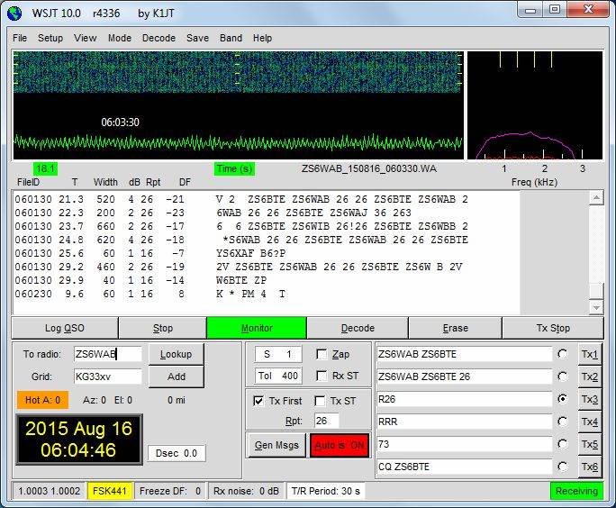
Worked
ZS6WAB, Willem in Polokwane (284.3 km) on 40.675 MHz FSK441
with big signals on the meteor scatter link.
Antenna: as above on a 6m pole
Rx/Tx:
IC-746 100W
A try on SSB yielded weak but
not copy-able signals in both directions indicating poor tropo
scatter conditions.
Two beacons on 6 and 4m
located near ZS6WAB could not be copied at all on a high gain antenna.