Dual Band Yagi for 50 and 70 MHz
©ZS6BTE September 2011
This antenna was designed
to operate on the 50 and 70 MHz bands, using a single feeder cable with a
direct 50 ohm match to the driven element thereby eliminating matching losses.
There is no direct
connection to the 70 MHz array and coupling is by critical spacing and length
of the 70 MHz antenna elements.
The antenna was intended
to be 7m long, but NEC modeling indicated lengthening the boom by 0.7m an
additional 1 dB of gain could be achieved on 4m. This is significant where a
rule of thumb dictates a doubling of a Yagi’s boom length to obtain 3 dB of
additional gain.
It was important that the
50 MHz performance matched that available from the best 7m boom class Yagis in terms of gain, lobe performance and SWR. This was
achieved. Depending on where the SWR is set, it is as low as 1.1 in the 50 MHz
band.
The antenna may be used as
a 50 MHz monobander, without penalty, by simply leaving off all the 70 MHz
elements.
Since 70 MHz DX is
available as far south as KG33 (Johannesburg area) only on TEP or F2 propagation
during solar maxima, and then sparingly, I was prepared to compromise a bit on
70 MHz lobe performance provided gain was high. Even so, the 4m performance is
good as can be seen from the diagrams. The SWR bandwidth on 70 MHz is rather
narrow and tuning up for best SWR by adjusting the length of the 70 MHz exciter
element is sharp and a change of only 2mm in overall length of this element
(element 4) is significant. When matched, the calculated SWR is low. Bear in
mind certain countries have 4m allocations just below 70 MHz, but most activity
at this time is around 70.1-70.2 MHz and the antenna will manage this,
depending on where the SWR is set, as can be seen in the summary table.
Although the mast boom and
antenna boom should be earthed, the elements are floating above ground and
appropriate precautions must be taken during thunderstorms.
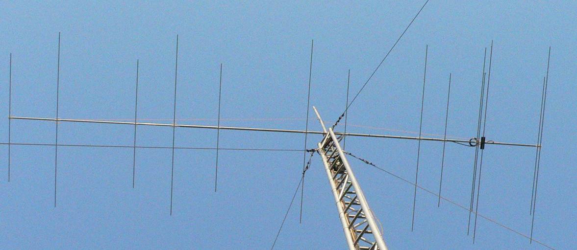
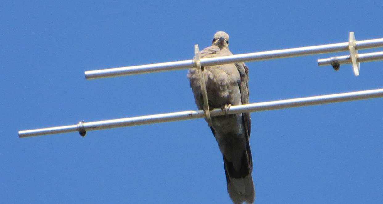
Overall view of 14 element dual band Yagi as installed
Construction details
12.7mm o/d x 1.22mm wall
thickness commercial grade aluminium was used.
All elements should be
insulated from the metallic boom by around 13mm, the nominal element diameter
(I used 10mm Perspex slabs).
Length and spacing must be
closely adhered to, and the length/spacing details around the reflector and
exciter elements, particularly, are critical.
Elements #3 and #4 must be
cut a bit shorter; then the ends slit to enable clamping with small hose clamps
to fasten telescoping 9.5mm aluminium tubing once the correct SWR points have
been found on each band.
If the antenna is mounted
with the feed point facing down it prevents crud building up across the
contacts.
Ideally a few turns of
coax should be tightly wound around the hand and fixed with cable ties
immediately before the feed point to act as a current balun to keep RF off the
outside of the cable, see photo above.
Alternatively, the cable
may be closely run along the grounded antenna boom and mast boom for a few
meters with cable ties. This also
provides significant impedance and a grounding path to RF on the outside of the
cable.
Elements 3-5 need to be
held apart by plastic spacers (strips of Perspex with holes drilled were used)
to prevent the 70 MHz SWR rocketing due to increased spacing as soon as the
antenna is hoisted.
The boom consists of 4m
long 25mm al square tubing in the centre portion and 20mm al square tubing
pop-riveted inside this to make up the end lengths. Such a structure bends much
under its own weight, so 2mm plastic line was used as “hangers” to suspend the
boom in place horizontally.
Tune up
There is no tune up in the
true sense. One simply adjusts element 3 first (Table 2) to set the 50 MHz SWR,
then element 4 to set the SWR on 70 MHz. To accomplish this ALL devices to be
used must be on line before trying the set the SWR point and these cables and
devices must be maintained during future use.
During SWR matching I found that 1.1 was possible on 50 MHz, and the
overall length of the 50 MHz driven element then exceeded that of the reflector
element. This increases the gain slightly and will degrade the rear lobe
performance marginally, but the IC-746 rig was happy at a first pass SWR of 1.5
so the SWR was left there to use the enhanced rear lobe performance.
Performance in use
On 50 MHz the <1.6 SWR
bandwidth as tuned exceeded 2.3 MHz (Table 1). The antenna has obvious
directivity and improved rejection of local noise compared to my 6.8m long 5
element Yagi used previously.
On 50 MHz a local beacon
on 50.050 MHz was attenuated more than 6 s-units off the back of the antenna to
noise level.
On 70 MHz a local beacon
on 70.009 MHz was attenuated more than 7 s-units off the back of the antenna to
noise level and around 6 s-units on the rear lobes.
Best SWR on 70 MHz was
1.15 (Table 1.) The transverter used put out full
power into this SWR without heating.
Table 1: Summary
of performance as modeled
|
50 MHz
band |
70 MHz
band |
|
|||||||||
|
MHz |
Gain, dBi |
Fr/back ratio, dB |
Fr/rear ratio, dB |
SWR 50 ohms |
SWR Measured* |
MHz |
Gain, dBi |
Fr/back ratio, dB |
Fr/rear ratio, dB |
SWR 50 ohms |
SWR Measured |
|
48.2 |
10.9 |
11.2 |
11.2 |
1.17 |
1.2 |
69.0 |
11.9 |
16.9 |
12.7 |
1.66 |
1.2 |
|
50 |
11.9 |
53.6 |
25.7 |
1.39 |
1.3 |
69.9 |
13.3 |
27.4 |
13.1 |
1.24 |
1.15 |
|
50.1 |
12.1 |
43.5 |
25.9 |
1.45 |
1.3 |
70 |
13.5 |
26.3 |
13.4 |
1.1 |
1.15 |
|
50.2 |
12.1 |
33.7 |
26.8 |
1.51 |
1.5 |
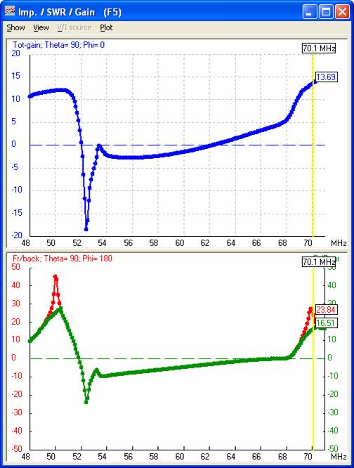
70.1 |
13.7 |
23.8 |
13.5 |
1.2 |
1.3 |
|
50.5 |
12.1 |
25.1 |
25.1 |
1.8 |
1.6 |
70.2 |
13.9 |
21.7 |
13.7 |
1.56 |
1.5 |
|
50.8 |
12.0 |
20.2 |
20.2 |
2.4 |
2.0 |
70.3 |
14.1 |
20.1 |
13.8 |
2.2 |
2.5 |
|
51 |
11.8 |
17.1 |
17.1 |
3.3 |
2.6 |
70.4 |
14.3 |
18.7 |
13.9 |
3.5 |
>3.0 |
*could be further reduced if
necessary by lengthening the telescoping elements
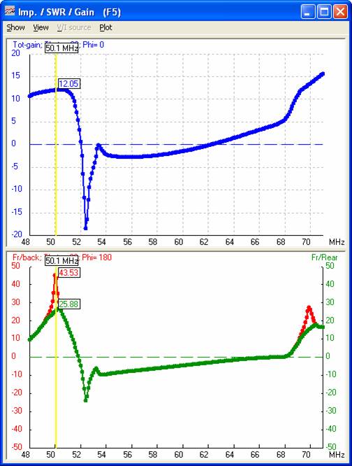
Gain and lobes at 50.1 MHz Gain
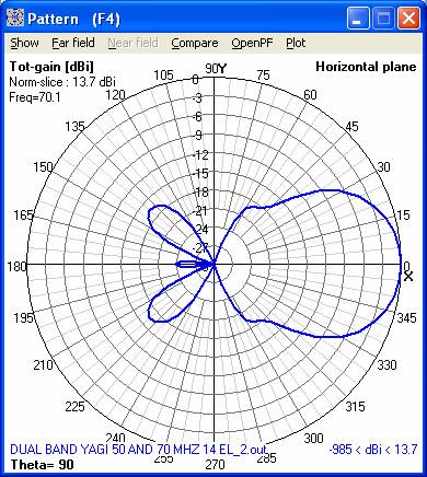
and lobes at 70.1 MHz
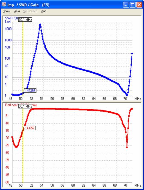
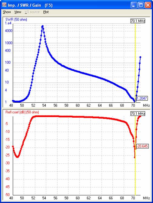
SWR at 50.1 MHz SWR
at 70.1 MHz
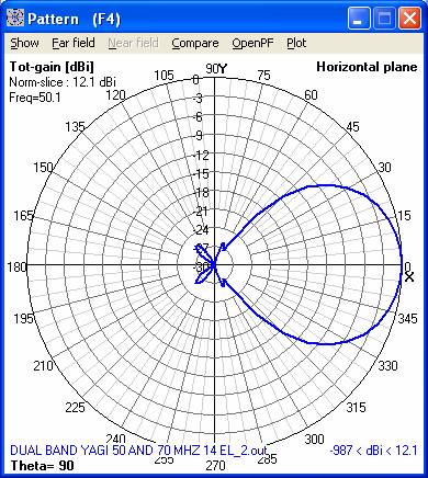
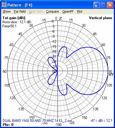
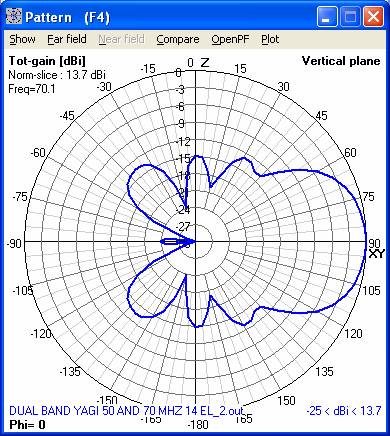
50.1 MHz polar diagrams
70.1 MHz polar diagrams
Table 2
Element parameters as modeled, all elements
insulated from the boom by at least 10mm
|
Element # |
Description |
Spacing from rear |
Overall length |
Other information |
|
|
1 |
6m
reflector |
0 |
2.966 |
add 20mm to
boom for rear overhang |
|
|
2 |
4m
reflector |
0.040 |
2.082 |
|
|
|
3 |
6m driven |
0.870 |
2.946 |
Split in
middle, shorten ends and slit* |
3.030
overall as installed |
|
4 |
4m exciter |
0.941 |
2.112 |
Shorten
ends and slit** |
2.013
overall as installed |
|
5 |
6m exciter |
0.965 |
2.800 |
|
|
|
6 |
4m director
1 |
1.444 |
1.984 |
|
|
|
7 |
6m director
1 |
1.812 |
2.758 |
|
|
|
8 |
4m director
2 |
2.908 |
1.892 |
|
|
|
9 |
6m director
2 |
3.467 |
2.684 |
|
|
|
10 |
4m director
3 |
4.732 |
1.862 |
|
|
|
11 |
6m director
3 |
5.364 |
2.610 |
|
|
|
12 |
4m director
4 |
5.917 |
1.852 |
|
|
|
13 |
6m director
4 |
7.041 |
2.522 |
|
|
|
14 |
4m director
5 |
7.723 |
1.852 |
add 20mm to
boom for front overhang |
|
|
boom |
|
|
|
overall
boom length = 7.763 |
|
* this element is driven at the centre,
shorten by 50mm each end, slit, insert a piece of 9.5mm al tube, length tunes
SWR
** shorten by 30mm each
end, slit, insert a piece of 9.5mm al tube, length tunes SWR
Details of tuning lengths and plastic
spacers required
Usage Notes
I was surprised by the 50
MHz bandwidth of 2.3 MHz. This is new to me; previously my h/brew optimized Yagis could only manage about 200 kHz.
Although the elements are
floating, static during a thunderstorm is about the same as a Yagi using grounded elements. It seems static charge will
leak off the antenna and mast boom regardless of whether the elements are
grounded or not, and the racket reaches the receiver anyway.
In a 6m TEP contact with
A92GR, he mentioned my signal being the strongest from ZS – I pointed out to
him a linear running legal power was in use; notwithstanding this the fact does
indicate high forward EIRP.
On 70 MHz a meteor scatter
QSO was completed with ZS2ACP at first try over a distance of about 870 km.
This was also the first contact on 70 MHz using this antenna. My transverter was running 20W at the time. This was conducted
when the antenna was wet following rain so the SWR was high at 3:1. As the
antenna dried the SWR decreased allowing the transverter
to increase power. This emphasizes my recommendation regarding spacing the
driven and exciter elements using insulators – this should be regarded as
mandatory in this antenna design.
Subsequently TEP contacts
were made with stations in
The antenna has realized
my expectations regarding its performance.
Other information
As far as 70 MHz
performance is concerned, have a look at the data on various antennas here,
note they all require some form of matching, deduct around 0.5 dB from their
gain claims accordingly:
http://www.70mhz.org/index.php?categoryid=6&p2_articleid=286
below (comments from that author):
Comparison table
After gathering information on all the 4m beams produced inside and outside
the
|
Model |
El. |
Boom (m) |
MMANA gain (dBd) |
Zo (Ω) |
Matching |
Connect. |
Weight |
|
EU (€) inc. post |
|
Moonraker YG5-4 |
5 |
2.62 |
7.8 |
50 |
gamma |
|
5kg |
70 |
144 |
|
DK7ZB |
3 |
1.3 |
5.7 |
28 |
λ/4 coaxial |
|
|
|
|
|
DK7ZB |
4 |
2.55 |
8.2 |
12.5 |
λ/4 coaxial |
|
|
|
|
|
DK7ZB |
5 |
3.2 |
8.5 |
28 |
λ/4 coaxial |
|
|
|
|
|
DK7ZB |
6 |
5.1 |
10.1 |
28 |
λ/4 coaxial |
|
|
|
|
|
DK7ZB |
7 |
6.5 |
10.8 |
28 |
λ/4 coaxial |
|
|
|
|
|
DK7ZB |
9 |
10 |
12.3 |
28 |
λ/4 coaxial |
|
|
|
|
|
Trident 4M4L |
4 |
3.2 |
8.7 |
50 |
hairpin |
N |
4.5kg |
110 |
333 |
|
HB9CV +2 |
4 |
2.26 |
7.7 |
50 |
gamma |
|
|
|
|
|
HB9CV+2 |
4 |
3.2 |
9 |
50 |
gamma |
|
|
|
|
|
Eagle 4M3DX |
3 |
1.67 |
7 |
50 |
balanced T-Match |
N/SO239 |
|
79 |
179 |
|
Eagle 4M4DX |
4 |
3.04 |
7.8 |
50 |
balanced T-Match |
N/SO239 |
|
95 |
202 |
|
Eagle 4M5DX |
5 |
3.8 |
9.1 |
50 |
balanced T-Match |
N/SO239 |
|
125 |
245 |
|
Eagle 4M6DX |
6 |
4.93 |
10.3 |
50 |
λ/2 coaxial |
N/SO239 |
|
139 |
265 |
|
Eagle 4M8DX |
8 |
8.51 |
12.2 |
50 |
λ/2 coaxial |
N/SO239 |
|
180 |
324 |
|
ZX yagi ZX4-3 |
3 |
1.4 |
6.5 |
50 |
gamma |
N |
|
|
175 |
|
ZX yagi ZX4-6 |
6 |
5.3 |
10.2 |
50 |
gamma |
N |
|
|
242 |
NEC simulation
NEC
file:
CM
file "DUAL BAND YAGI 50 AND 70 MHZ 14 el.nec"
CM
dual band yagi 50/70 MHz, driven el is simple dipole,
direct feed – no matching needed
CM
Elements 12.7mm; insulated from boom
CM
predicted performance:
CM
50.1 MHz SWR 1.2, Gain 12 dBi, b/f and f/r 40.6/26.3
dB.
CM
70.1 MHz SWR 1.37, Gain 13.9 dBi, b/f and f/r 24/16.5
dB
CM
Set 50 MHz SWR first, then 70 MHz SWR.
CM
Tuning 50.1: cut element 3 (50 driven element) 50 mm short each side, slit,
insert 9.5mm al tube,
CM
tune for best SWR. Clamp.
CM
Tuning 70.1: cut element 4 (70 exciter) 30 mm short each side, slit, insert
9.5mm al tube,
CM
tune for best SWR - 2mm overall is relevant. Clamp.
CE
SY
refl=1.483
SY
ref7l=1.041'70
SY
ref7sp=0.040'70
SY
drivsp=0.870
SY
drivl=1.473
SY
drivl7=1.056'70 exciter
SY
drivsp7=0.941'70 exciter
SY
driv2l=1.400'50 exciter
SY
driv2sp=0.965'50 exciter
SY
dir17l=0.992'70
SY
dir17sp=1.444'70
SY
dir1sp=1.812
SY
dir1l=1.379
SY
dir27l=0.946'70
SY
dir27sp=2.908'70
SY
dir2l=1.342
SY
dir2sp=3.466856
SY
dir37l=0.931'70
SY
dir37sp=4.732'70
SY
dir3l=1.305
SY
dir3sp=5.364
SY
dir47l=0.926'70
SY
dir47sp=5.917'70
SY
dir4l=1.261
SY
dir4sp=7.041
SY
dir57l=0.926'70
SY
dir57sp=7.723'70
GW 1
13 0.000 -refl 0.000
0.000
refl
0.000 0.0065
GW 2
9 ref7sp -ref7l
0.000 ref7sp ref7l
0.000 0.0065
GW 3
19 drivsp -drivl 0.000
drivsp
drivl
0.000 0.0065
GW 4
14 drivsp7 -drivl7
0.000 drivsp7 drivl7
0.000 0.0065
GW 5
17 driv2sp -driv2l
0.000 driv2sp driv2l
0.000 0.0065
GW 6
15 dir17sp -dir17l
0.000 dir17sp dir17l
0.000 0.0065
GW 7
15 dir1sp -dir1l
0.000 dir1sp dir1l
0.000 0.0065
GW 8
15 dir27sp -dir27l
0.000 dir27sp dir27l
0.000 0.0065
GW 9
15 dir2sp -dir2l
0.000 dir2sp dir2l
0.000 0.0065
GW 10 15
dir37sp -dir37l 0.000
dir37sp dir37l 0.000
0.0065
GW 11 15
dir3sp -dir3l 0.000
dir3sp dir3l 0.000
0.0065
GW 12 15
dir47sp -dir47l 0.000
dir47sp dir47l 0.000
0.0065
GW 13 15
dir4sp -dir4l 0.000
dir4sp dir4l 0.000
0.0065
GW 14 15
dir57sp -dir57l 0.000
dir57sp dir57l 0.000
0.0065
GE 0
FR 0
1 0 0 50.100
0.00E+00 0.00E+00 0.00E+00 0.00E+00 0.00E+00
EX 0
3 10 0
1.00E+00 0.00E+00 0.00E+00 0.00E+00 0.00E+00 0.00E+00
RP 0 1 360 1510 90. 0. 0. 1. 0. 0.
EN