Bi-directional Yagi for 144 MHz
ZS6BTE 4 Jan 2016
This antenna addresses a special purpose, where a rotator is not available or required, yet operation from two directions (off the front and back of the antenna) is needed.
The antenna is driven at the centre-most element with 50 ohm coax feeding a 4:1 balun to provide an impedance of 200 ohms. The predicted SWR is 1.1
To keep the overall length down to less than 5m (4.8m in fact), the number of elements was restricted to 9 including the driven element.
Tuning
During construction, make the driven element somewhat longer than specified, then progressively shorten until best SWR is achieved. All cables, etc, should be attached at the time of setting the best SWR. The impedance is mostly pure resistance at 183 ohms, with low reactance, Fig 1.
The 4:1 balun will keep RF off the outside of the coax as well as maintaining the necessary high impedance of ~200 ohms at the feed point of the antenna.
Best Gain
Gain is good at 11.9 dBi for what is essentially a 5-el Yagi and of course there is no back-to-front ratio as the antenna's pick-up from the "front" is mirror-imaged at the "rear", with good symmetry.
During installation adjust the height above ground in the order of half wavelength or so to peak up a DX signal. This will provide some ground gain providing total gain in excess of the modeled prediction, by as much as 3 dB typically, and also prevent anti-phase pickup from ground reflections in the wanted directions which could nullify much of the gain.
Noise Performance
With no back-to-front ratio this antenna will collect noise pickup from two directions and appear very noisy. Even so, the lobe performance in the horizontal plane, Fig 5, is good at more than -15 dB down, which will match the performance of most uni-directional Yagis, but in the vertical plane, Fig 6, the worst lobes are only ~10.3 dB down, which is not all that bad on a special-purpose antenna such as this.
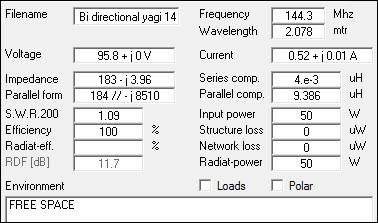
Fig 1: Essential parameters
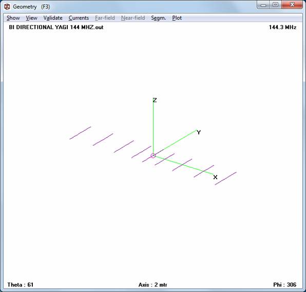
Fig 2: Geometry. Driven element plus 8 directors
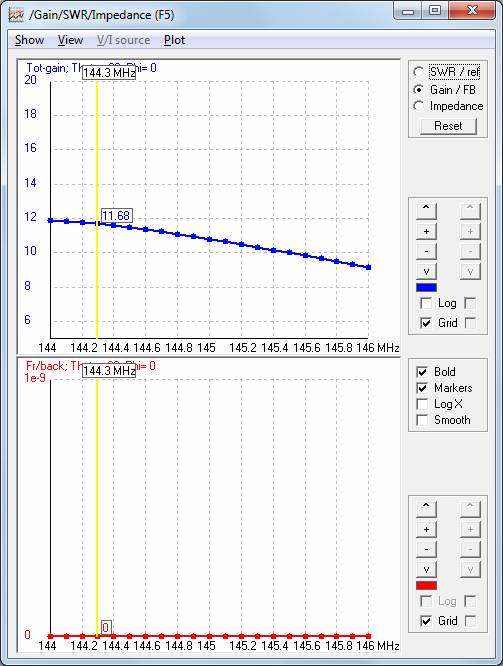
Fig 3: Bi-directional Gain
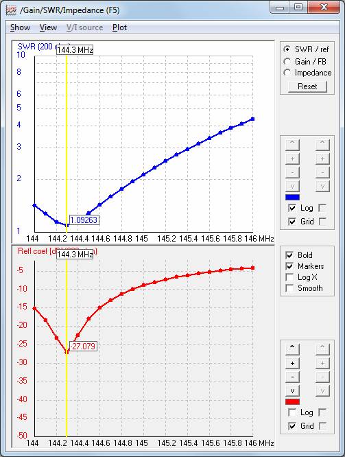
Fig 4: SWR at 200 ohms (use a 4:1 balun)
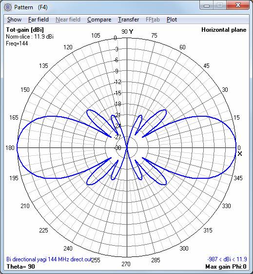
Fig 5: Horizontal pattern at 144 MHz
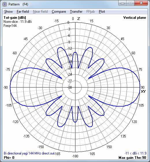
Fig 6: Vertical pattern at 144 MHz
Construction
Element lengths in the NEC file below are half lengths (and free space dimensions, where the elements are mounted on insulators). The overall length to cut an element is twice this. If they are to be grounded to the metal boom, add 66% of the boom's diameter to the overall length:
so the length for director 1 grounded on or in a 25mm sq boom is (0.4507 x 2)m + (25 x 0.66)mm = (0.9014m) + (16.5mm) = 0.9179m.
Use 25mm sq alu tube, for grounded elements drill holes through this tube to locate the element spacings. Correct the element lengths according to the diameter of the boom. Polish all joints to a shine with a stainless steel brush. Then aluminium solder (NOT braise - too much heat) these elements in place both sides of the boom using a LPG torch or a soft oxy-acetylene flame. The driven element is a simple dipole, mounted on some plastic to insulate it from the boom. The mechanical balance point is at the driven element, it will be a good idea to offset the mounting point to the mast a bit the keep the feed point away from the mast boom. Ground the boom to the mast, which should also be grounded for safety.
Notes
This antenna has not been constructed by me.
NEC File
CM NEC Input File of "bi directional yagi.nec"
CM 11.9 dBi gain, b/f ratio 0 dB. SWR in 200 ohms 1.1. Elements 5 mm ungrounded on the boom. Length 4.92m.
CM Use 5 mm alu rod for the elements.
CM Free space dimensions, add the element length correction for the metal boom (~66%) if elements are grounded on the boom.
CE Eight directors needed. Overall length 2.4035 x 2 meters
SY drlen=0.489531 'driven element half length meters
SY dir1len=0.450701 'director 1 half-length meters
SY dir1sp=0.391029 'director 1 spacing from driven element meters
SY dir2len=0.455359 'director 2 half-length meters
SY dir2sp=0.963761 'director 2 spacing from driven element meters
SY dir3len=-0.46407 'director 3 half length meters
SY dir3sp=1.66629 'director 3 spacing from driven element meters
SY dir4len=0.483938 'director 4 half length meters
SY dir4sp=2.4035 'director 4 spacing from driven element meters
GW 2 11 0.000 -drlen 0.000 0.000 drlen 0.000 0.0025
GW 6 11 dir1sp -dir1len 0.000 dir1sp dir1len 0.000 0.0025
GW 3 11 dir2sp -dir2len 0.000 dir2sp dir2len 0.000 0.0025
GW 4 11 dir3sp -dir3len 0.000 dir3sp dir3len 0.000 0.0025
GW 5 11 dir4sp -dir4len 0.000 dir4sp dir4len 0.000 0.0025
GW 8 11 -dir1sp -dir1len -0.000 -dir1sp dir1len -0.000 0.0025
GW 9 11 -dir2sp -dir2len 0.000 -dir2sp dir2len 0.000 0.0025
GW 10 11 -dir3sp -dir3len 0.000 -dir3sp dir3len 0.000 0.0025
GW 11 11 -dir4sp -dir4len 0.000 -dir4sp dir4len 0.000 0.0025
GE 0
FR 0 1 0 0 144.3 0.00E+00 0.00E+00 0.00E+00 0.00E+00 0.00E+00
EX 0 2 6 0 1.00E+00 0.00E+00 0.00E+00 0.00E+00 0.00E+00 0.00E+00
RP 0 1 360 1510 90. 0. 0. 1. 0. 0.
EN