Having the opportunity of using a solid state PA for the 6m Magic Band I had the problem of avoiding to damage it with the power spikes emitted by my ICOM IC-706 MKIIG. See the site of Leif SM5BSZ http://www.sm5bsz.com/dynrange/alc_ic706.htm for more details.
The PA needs only 10W to deliver its 800W. One possibility was to use an attenuator to dissipate 70 of the 80W delivered by the IC-706.
A second possibility was to use an external adjustable negative tension connected to the ALC of the IC-706.
A third alternative, as suggested by the same Leif, was to use a directional coupler with 8.45 dB of difference between the two outputs.
The extra 70W can be destroyed into a dummy load or, better, added to the PA output with a second directional couppler.
What is presented here is the first directional couppler, done with lumped components and a guide to design similar ones.
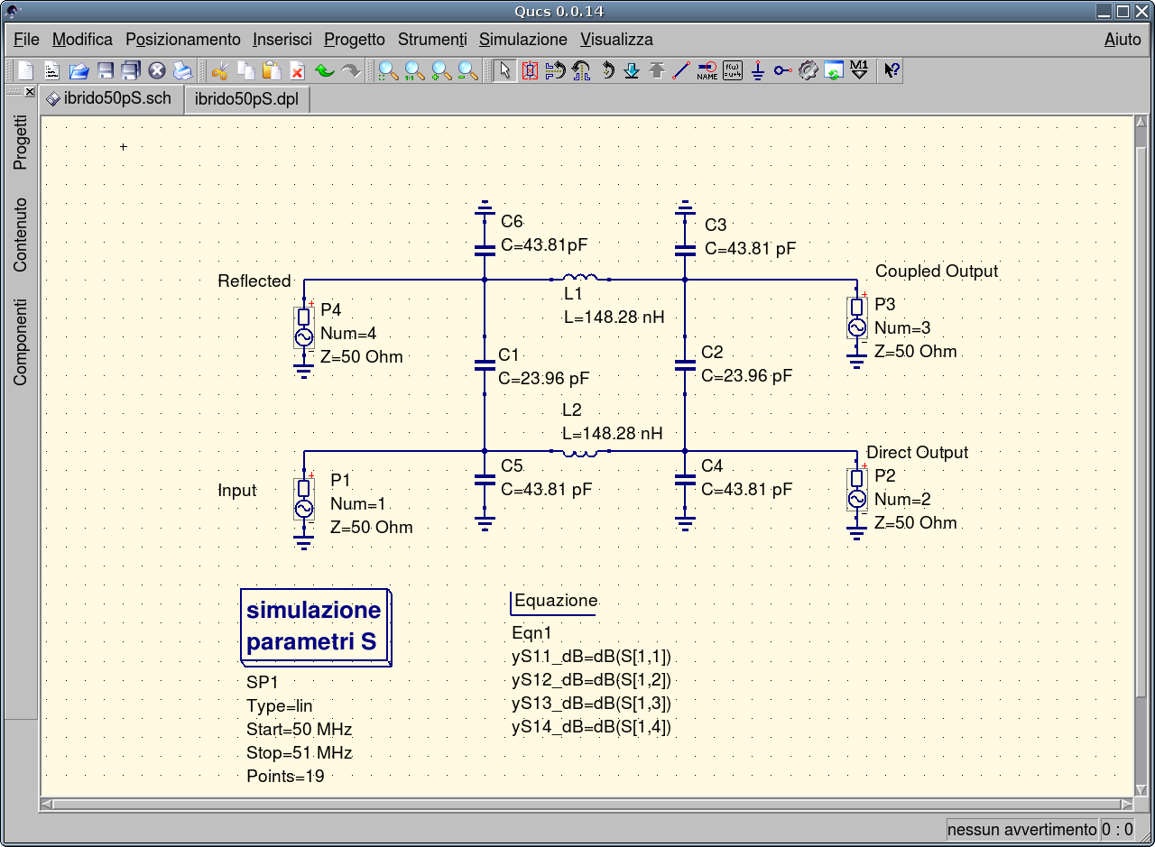
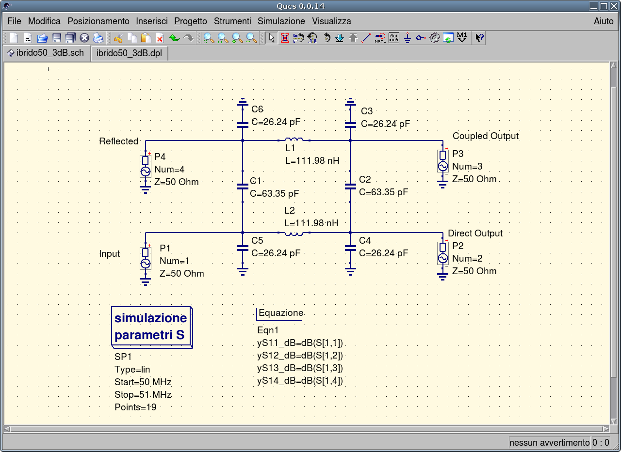
The following picture shows the directional coupler as analysed by Qucs.
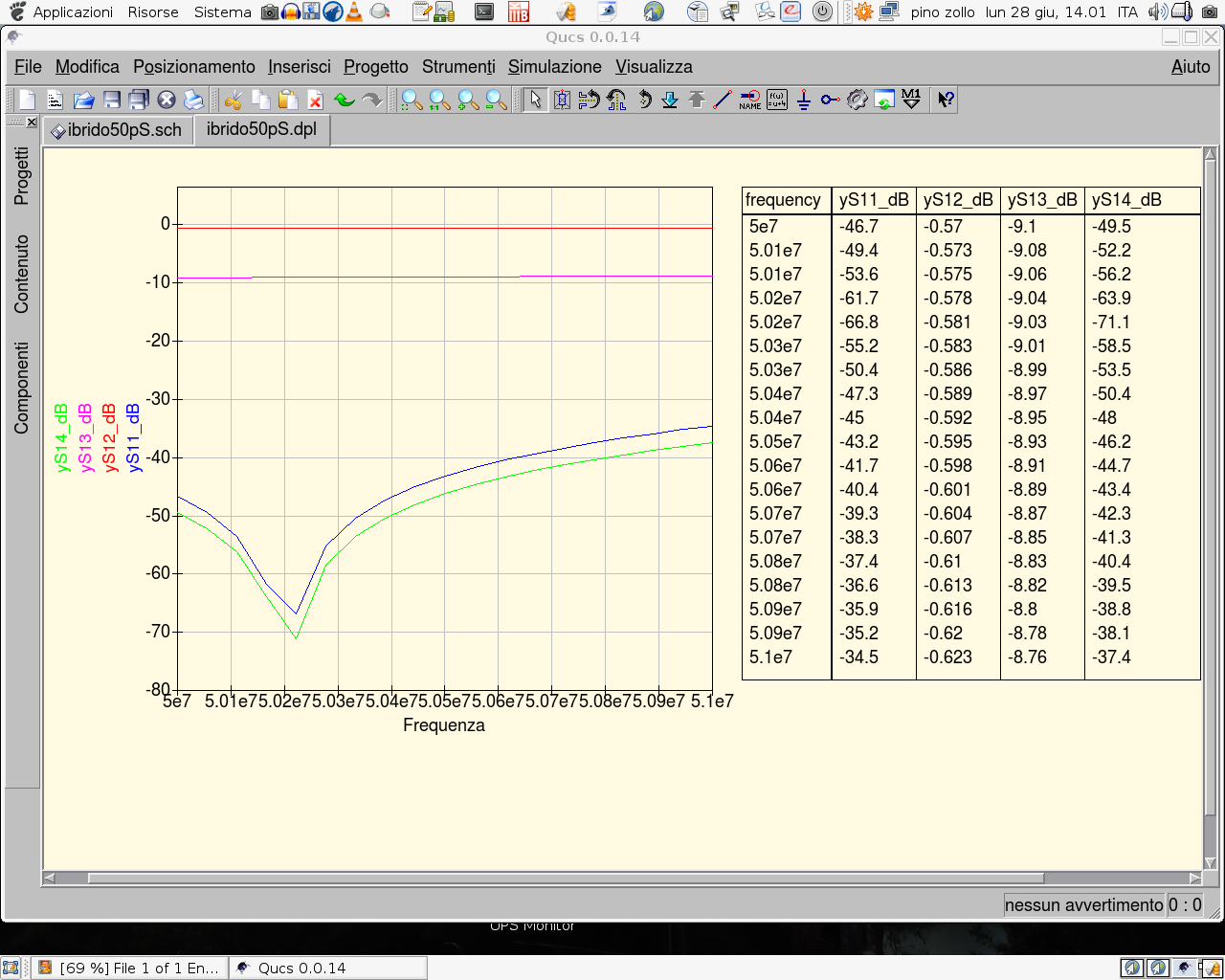
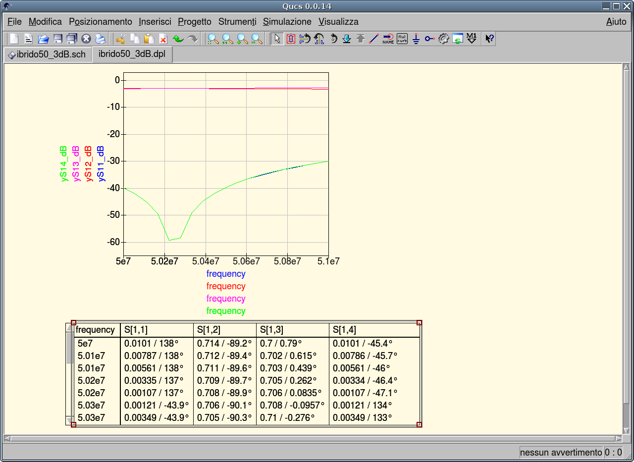
The following shows the results of the simulation.
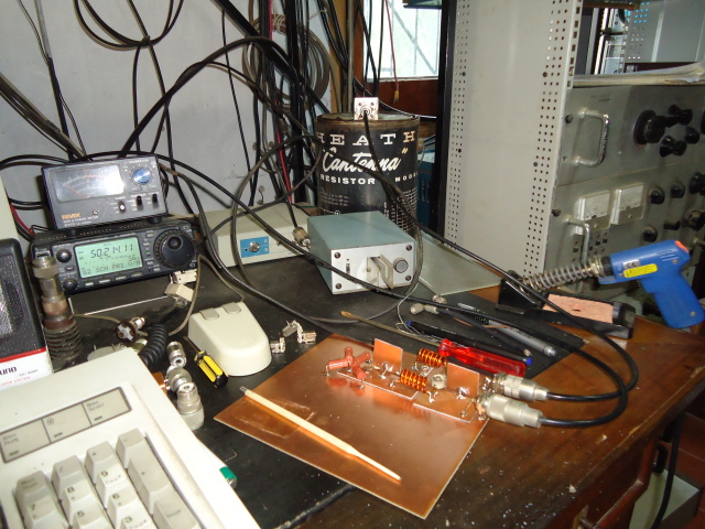
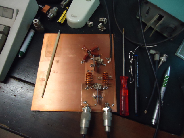
The prototype has been implemented on a PCB where the four equal capacitors to ground have been made by pieces of single layer PCB, and the two capacitors between the branches have been made by 2-layers PCB pieces.
Note the two variable capacitors to fine adjust the coupling.
The reflected power is dissipated into a 50 Ohm load made of two 220 Ohm and two 180 Ohm not inductive resistors.
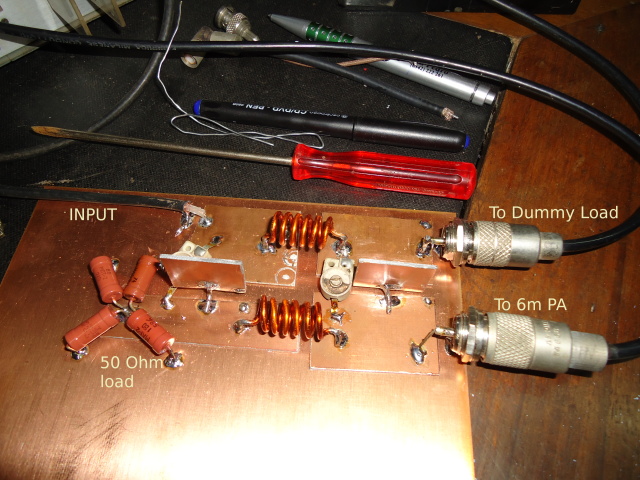
Photos of the protopype
Qucs has been used for verifying the project of the directional coupler. Here are the files: ibrido50pS.sch ibrido50pS.dpl ibrido50pS.dat
Put 0 dB for a "3db Coupler" i.e. 3dB between the input and the output, but 0 dB between the two outputs.
This last one is very useful for feeding two antennas as the directional coupler is both a splitter and a summer. Note the two outputs are 90° out of phase, so suitable for circular polarization.