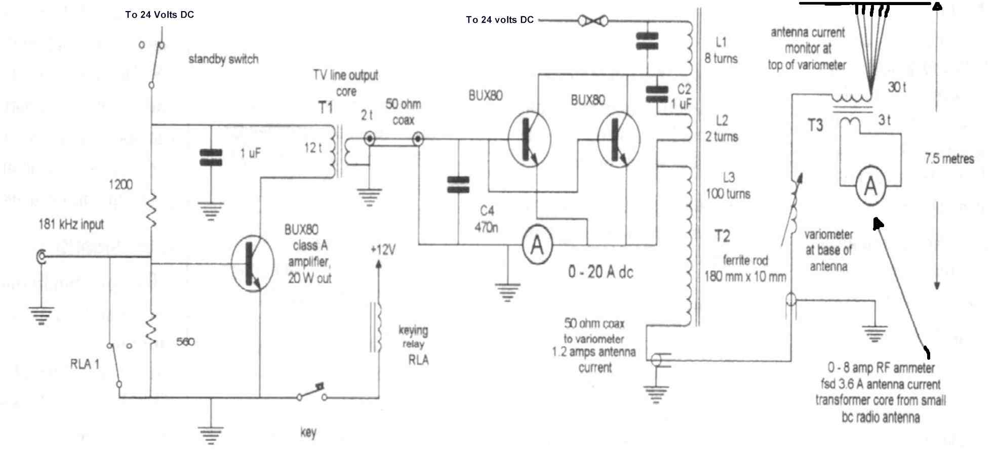
My 1997 Transmitter, less the 181khz exciter.
In 1995 I became interested in LF
experiments. This involved designing and constructing a Low Frequency
transmitter.
A small group of ZLs conduct twice weekly on air tests on the
allocated ZL LF band 165khz to 190khz. A permit is required to
operate an experimental station on this band, and some special
conditions apply. One being the 5 watts EIRP transmitter power
limit.
The amateur activity in ZL happens around 181 Khz.
My 1997 Transmitter, less
the 181khz exciter.
The above transmitter was the result of
many hours of trial and error.
In fact, rather a lot of error. I blew up a about 10 final
transistors before deciding on the BUX80s. These are inexpensive
and easily obtainable here. The above circuit, explanation of it
and Editor's comments, was published in "Break-In",
the journal of the New Zealand Assn. of Radio Transmitters in
September 1997. I later modified it to run off 48 volts and added
a further two output transistors. Then producing a power output of
about 200 watts.
Constructing efficient antennas is one of the real challenges for LF experimenters. My best attempt had a vertical section of 7 metres height and 100 metres of "Top loading" wire. This "Top loading" was strung about my small plot of land using what few trees there were available. Unfortunately when high winds were blowing the trees moved and the antenna fell down. This happened many times. This antenna did however perform well enough to allow myself and ZL1WB to conduct regular QSOs using CW mode over the mainly sea path to his QTH in Whangarei a distance of over nearly 400 miles (600 km). The aerial current measured here was about 1.5 amps of RF.
I experimented with various forms of antenna including tuned loops for transmitting. Though some of these loops had an area of about 60 square metres they proved to be very poor for transmitting. Though they performed well on receive.
The conclusion I drew from my many experiments was that:
You cannot do better than go back to the basics of LF / MF antenna design that were worked out by the pioneers of radio in the early 20th century.
That is:
To have as much vertical component as possible.
To have as much "Top loading" as
possible.
To have an efficient "earth" system in
the form of many radials of wire in the ground.
To reduce ohmic losses to the
absolute minimum.
The following picture and text refers to shipboard transmitting antennas, but well illustrates the principles for an amateur LF antenna system.
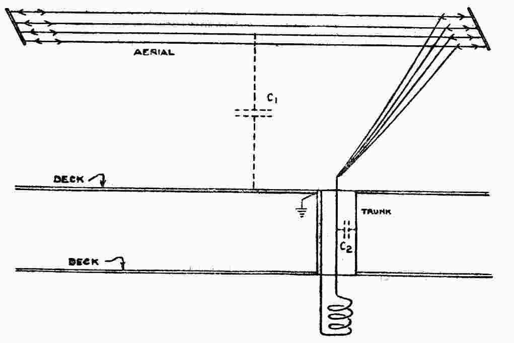
The above
drawing and following text are from
the 1938 Admiralty Handbook of Wireless Telegraphy Vol.II.
"In order to have a big radiating capacity, the roof system of wires should have the greatest possible area. Two wires hoisted up parallel to and at a considerable distance from one another, will have a capacity nearly twice that of a single wire, but as the wires approach one another the joint capacity becomes less, so that when they are within (say) a foot of each other, very little extra capacity is gained by the use of the second wire. A few wires spaced far apart are better than many wires near together, so far as total capacity is concerned. It is bad practice to bring a portion of the aerial low down with the idea of increasing the capacity, although the latter is necessary for frequency range; the decrease in radiation height far outweighs the advantage of any increase in capacity."
However what is a good antenna for transmitting is not necessarily good for receiving. There is a point where the large and relatively efficient transmitting LF antenna becomes very "noisy" on receive. In that it has so much wire in the air that it is picking up lots of atmospheric noise. So perhaps the ideal LF station may have a physically large antenna for transmitting and a small "active' antenna for receiving. Many of the ZL experimenters are using active antennas for receiving.
Because LF antennas are so very inefficient
it is necessary to run as much power as possible.
Regarding what is sufficient power. I would say that measuring
the RF amperage at the base of the antenna is the best way to
determine what is going out into the "ether" (to use an
old term) and a measurement of two amps RF is a good level to aim
for. To get this amperage in your antenna a DC input power of 200
watts or more may be required. Depending on the efficiency of
your RF power transfer system.
Instruments that measure RF power at LF are difficult to find. I resorted to using light bulbs, and estimating the power from the lamp brightness! The last transmitter I built was tested into a 250 watt 230 volt domestic light bulb. This has a fairly low impedance. Some ZL amateurs have tried using oil filled 230 volt domestic night storage heaters for "dummy" loads with some success!!. Of course these will only be suitable for really high power transmitters.
Much depends on where your nearest active
LF amateur lives. My nearest active amateur is only 90 miles
away, but over a difficult ground-wave path. My best DX is also
the easiest path 400 miles over the sea.
Presently ZLs are trying to communicate with VKs on LF. but
though each country has heard the other there has been only a
single two way contact. Much depends on the ground wave path and
the amount of amateur activity. Amateur activity is governed by
the regulations of that country as well as it's amateur
population. Sometimes the regulations in one country may not
allow common frequencies to be used between countries. In ZL it
is relatively easy to get a LF transmitting permit. However I
believe that in Australia/VK it is difficult.
Receiving is far easier than transmitting, that is for sure.
You may be suprised to hear that amateurs in ZL can copy the
Galveston, Texas radio beacon "GLS" on 206 khz. A
distance of over 12,000 km!
Try listening for marine and aero beacons in the LF bands. For this you need a receiver that will cover the bands from 200 khz to about 400 khz. You will also need some knowledge of Morse Code as the beacons send their identification in morse code. For those who are not good at morse the good news is that the speed of the morse is very slow. A morse reading software package should be able to decode it for you if you really get desperate. The identification usually takes the form of a two letter callsign, sometimes three letters. This ID is repeated every few seconds, which should give plenty of chances to indentify the beacon.
To identify the beacons from their ID signals you could try looking in the ITU publication "List of radio determination and special service stations", or the Admiralty list of Radio Signals. Your national Nautical Almanac should also have a list of local radio beacons.
These beacon stations are built to provide
a certain minimum daytime "groundwave" coverage. The
maximum being about 100 nautical miles. However these quoted
ranges are very conservative, and with a good aerial and receiver
they can be heard over much greater distances. At night time they
can be heard via "skywave" many thousands of miles
away.
In
the New Zealand area try listening for the following beacons:
There are many others located at most
airports, and at significant points on the coast. Though the
marine ones are becoming less each year. Experiment with various
antennas, including small tuned loops.
Look at my "links" page to see where you may find
information.
Last update 01/02/02