Stereo sound systems
Stereo sound systems
FM stereo multiplexer layout
|
FM Stereo The bock diagram above shows the layout for simple FM stereo encoder. Audio input stage needs to have a frequency roll off at about 15 kHz. This is to provide space for the 19 kHz pilot carrier. Next step is the 50uSec pre-emphasis for improved signal to noise performance. The 4066 switch is there for alternate switching between to left and right sound channels. The combined signals at this point become a sum of two inputs. |
76kHz oscillator stage drives into a 4013 flip / flop output A is the drive for multiplex switch (4066). The other B is the pilot output drive. The 19kHz out is a square waveform and there for need to be clean up, this done via the pass band filter. The problem that I have come across with FM stereo is pilot carrier phase shift. It is very important to keep the pilot carrier in phase with the multiplex signal, for best stereo sound separation. This is why you have the ability to set the phase angle. The output stage combines the multiplex sound with the pilot carrier, then into a driver amplifier. |
FM stereo encoder circuit using a PIC16F84A
A2 stereo multiplexer layout
|
German A2 stereo Works with two FM sub-carriers one is 5.5 MHz the other is at 5.742 MHz. In stereo mode the left and right channels are combined into a sum of the two. Ie L + R / 2 this sum signal is then feed out to the 5.5 MHz sound sub-carrier. The other signal is the right channel information that combined with the 54.68 AM pilot carrier. This is feed out to the 5.742 MHz sound sub-carrier. |
In dual channel mode the two inputs are feed out separately on to the two sound sub-carriers. Same as before the 54.68 AM pilot carrier is feed out to the 5.742 MHz sound sub-carrier. In stereo mode the pilot carrier is modulated with 117.5 Hz sine wave at 50% modulation. In the dual mode the frequency is 274.1 Hz sine wave at 50% modulation.
|
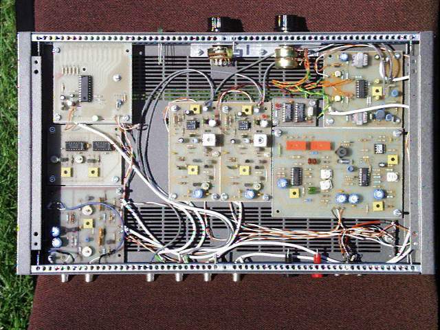
Above shows a photo of a build up encoder
You see above a simple circuit for encoding