
Fibre optics
RF to Optical
There exist possibilities to transfer an RF signal into a Fibre Optic cable or Dielectric waveguide. There are ways that this can be achieved by using digital or analogue methods. The simplest way is by using analogue modulation. This can done by using AM (Amplitude Modulation) or FM (Frequency Modulation) techniques.
Optical
emitters require a bias current, typically between 2 to 15 mA. By
switching the bias between 2 and 10 mA, this method can be used for
Digital and FM modulation. The emitter in some cases is nothing more
than an LED (Light Emitting Diode) that has it's light focused in a very
narrow beamwidth into an optical waveguide.
For AM you set the bias current at 7mA and amplitude modulate the bias between 2 and 12 mA. The modulation bandwidth is dependent on the internal capacitance of the emitter used. It is possible to have modulation bandwidth up to 6 GHz in frequency. RF can be sent along the Fibre optic cable for distances up to 6 km. The attenuation on an optical cable is the same at all of the modulated frequencies. This is where optical cable differs from coaxial cable; coaxial cable always has an amount of stray capacitance which will cause greater attenuation at higher frequencies.
For FM modulation you have a VCO (Voltage Controlled Oscillator), lets say at 70 MHz, which is modulated with audio or a video waveform. The method used is PWM (Pulse Width Modulation) where the width of the pulse is modulated. The emitter is modulated in the same way as digital where you are switching between two bias points. This why Digital and FM modulation systems work over a longer distances up to 70 km.
The detector converts the light back into an electrical signal, which is then amplified. The bandwidth of the detector is also limited by it's internal capacitance. There is two types of detector used, one will give a digital and the other analogue output. This is quite simple to emulate what is happening by using a lamp and an OC71 transistor. Remove the paint from the case of the transistor and let the light from the lamp shine into the base junction. This will change the bias on the transistor.
The are many possible uses for this technology, if you have a modulation bandwidth of 40 MHz to 2.5 GHz. All of the VHF and the UHF Television channels as well the satellite IF of 900 to 2150 MHz can be feed into the optical cable. It can also be used for a security surveillance system where a group or groups of video signals need to be fed from one building to the next. Other uses could be at repeater sites where there are two huts, one for receive and the other for transmit, using the Fibre optic waveguide to interconnect the two buildings.
Photo is of the optical AM modulator / demodulator
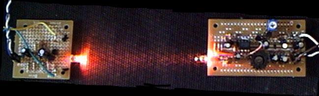
>The video waveform is inverted after the first transistor stage. This circuit uses a bootstrap follower as a simple modulator for LED or emitter. The sync pulses are at the peak current points. Adjusting the 1k pre-set will set the quiescent bias current for the emitter. This modulator is based on the design used in Wireless world dated August 1964 called 'The Light-emitting Diode'. Setting up LED / emitter bias current.>
Check the current rating for the device that you wish to use. If it is for example 40mA, you measure the voltage across the 1k pre-set to ground with a DC volt meter. By using ohms law you work out the bias current. Set the resistance for the correct amount of bias current.
I=V/R
4.8 volts / 120 ohms = 40mA
Using this calculation, the 1k pre-set and the 15-ohm resistor could be replace with fixed value of 120 ohms.
Types LED used
Sunset Red 616nm (Z-4031) good modulation bandwidth + light outputRuby Red 660nm (Z-4074) works well
Infra Red 940nm (Z-3235) poor frequency response
Modifications for de-modulator below
On the first transistor stage, change the collector resistor value from 2.2k to 3.3k and replace the BC547 transistor with one that has higher Ft, possibly an RF transistor. I have used a BFY90.
AM demodulator with AGC
The Phototransistor used was a BPV11 that I found at the local Dick Smith store (Z 1945). The bandwidth of this device is a problem when it comes to detecting a video waveform. There were three different types of phototransistors that I found and tried in this circuit. The ones that gave the best performance were the devices that had an external base connection. This is needed for external biasing to give improved linearity. Bandwidth verses gain of the transistor, since this device has a low frequency response a needed bias for wider frequency range over the gain. This is how I was able to detect video; the trade off is the signal to noise performance.
With the very limited baseband frequency response, adding in Sound sub-carriers onto this link would not practicable. But I am still looking for better-suited phototransistor to be used in this receiver design.
>All AM demodulators need some form of AGC (Automatic Gain Control) to avoid clipping of the waveform. First detect an AC level from the output stage of 2N2219A transistor. This signal is then fed into a diode voltage doubler, which biases the BC548, and in turn biases the MPF102 FET. In this part of the circuit there is a 20k-adjustment pot to set video output level. As the bias on the FET changes, the channel resistance changes which affects the gain on the NE592 op-amp's gain control pins.
Updated Transmitter design
I have made a number change to circuits above. On the transmitter I have replaced the LED with a Luxeon device, and change the drive transistor. The drive current for the Luxeon is now peaking at 600 mA when modulated.
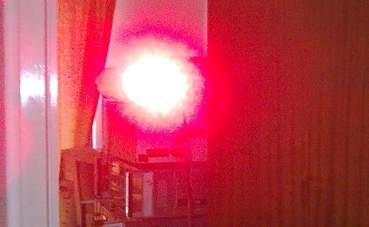
On the receiver side I replaced the phototransistor with a photodiode and preamplifier that is in build in the one case. This device is good frequency response up to about 20 MHz. The photo on the left is of my 630 nm transmitter. Taken from workshop door way and aimed down the hallway. The one below was taken 1 pm in the afternoon in natural light. You can still see the red light from my TX shining on the wall. If this light were to be aimed into my receiver at this distance it would go into overload.
The diagram below shows the transmitters optical layout in PVC tubing. Two tubes one inside the other do the focusing in a telescopic arrangement. The 90 mm reflector is out of six volt torch with the Luxeon mounted in the centre. The convex lens focuses the light to a spot, this need to set for the operating distance. This 100 mm lens comes out of a $2 magnifying glass.
On the receiver is much the same a convex lens focuses the light into the photodiode via 630 nm filter (red perspex).


Spectral response
As you can see from the graph the optermin wavelength the at 900 nm inferred range. Visible red is a 630 nm the detector will still operate at this wavelength.
Another thing I could do is replace the Luxeon with a two watt laser diode, at 800 nm.
Frequency characteristics
This shows the demodulated RF bandwidth of these two similar devices. This is where the limitations are, in the detector bandwidth. The next step would to find photodiodes that will operate up to 100 MHz.
Now with all the changes I have about 20 MHz bandwidth to play with. Like with videotape I decided to try frequency division multiplexing. I did this by putting together a simple Television modulator using a NE612 mixer IC. The circuit is not hard to contract; the NE612 has all the internal parts needed for an AM modulator. Since this IC is a double balanced mixer I added a 330k resistor to pin 2 to unbalance its mixer. By doing this you end up regenerating the carrier, the modulation level set by 100 ohm pre-set. The BC548 is an emitter follower, low impedance out stage to drive into 75 ohms.
The demodulator is an UHF TV turner. Mixed up from 12 MHz to about 500 MHz using a Dick Smith up converter kit (K-7621).

The photo shows my 12 MHz modulator on a piece of veroboard.