
Building and designing an ATV repeater
Background:
I started experimenting with ATV repeater set ups back in the late 1990s and soon found a large difference in performance between AM and FM systems, but at that stage I did not have the right test equipment to measure what I was seeing. About seven years ago I got a HP signal generator and this has provided me a means to understand what is going on with these different configurations.
Introduction:
In this article I will go over the results of these experiments. I have tested these three modulation systems; AM/VSB, FM, and QPSK. I will also go into ATV repeater design and the factors that need to be taking into account to provide for the best over all performance.
Inversion layers:
Band opening mostly happen in the Summer time due humid warm air mass rising, with a dry cold air mass above. This layer between is the Inversion layer, with this changing air density this affects VHF/UHF propagation providing DX opportunities. The greater the temperature and humidity the higher in frequency that can be worked. From experiments done, I found for every 10 band opening on 6m you may only get one on 23cm. A good way to predict when this is likely to happen is to check the local weather map and look high pressure systems forming across the area of interest. For DX on 23cm look for about 1010 hPa at 27c and 95% humidity or higher.
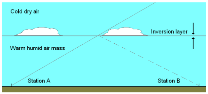
Signs to look out for with inversion layers; clouds with flatted bottoms or from built up area low down haze with clear sky above.
ATV long distance experiments using QPSK vs FM:
With Ralph ZL1TPG and myself, we soon found out under band enhancements conditions with fading (QSB) that we had no luck with QPSK as a DX mode, but we could see picture in the noise with FM showing the advantages of analog modulation. The trap that most ATVer fall into with QPSK is they try to do a auto scan on their Satellite receivers and scan over the wanted signal. Always setup your settings manually, Frequency, FEC, Symbol rate and PIDs this will give you a far better chance of getting a lock on DATV carriers.
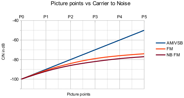
With AM you get a linear response with carrier to noise up to about 55dB for a P5 picture. This does not happen with FM, it's more of a S-curve. For FM I tested a bandwidth of 18MHz and I got for C/N of 26dB. Where by at 23dB carrier to noise I could get a P5 picture by limiting the demodulator frequency response.
AM/VSB
P1
|
FM
P2
|
FM
P3
|
FM
P4
|
FM
P5
|
At the P1 level I could make out sync in the noise with AM, but very little sign of it on a FM receiver. The cross over point happens at the P1.5 level where by both receivers provided much the same performance. Once I got to P3 on the FM there was very little change on the AM receiver, this comes back to the S-curve affect you get with FM demodulators. With AM you can use something like 8dB for each P point I like to use 10dB per P point, it's not important it's only based on a visual representation on what is seen to be displayed. With FM it's not so easy to workout P points due to the way the demodulator works, change can happen over a small amount of signal change.
Digital modulation systems:
The type of modulation system used is dictated by the form of propagation that is used. This is why there is large range of narrow band digital mode out there you can run on your computer. Each digital mode is design to work under certain proportional conditions, therefore the modulation systems are very closely link to propagation. Is also applies to DATV there is two modulation systems that have be designed to work across free space there are: DVB-T/T2 and DVB-S/S2. Where by DVB-T/T2 uses a COFDM as it modulation and because of this it has very good immunity to multipath. The DVB-S/S2 (QPSK/8PSK) format is design as an up and down linking for Satellite broadcasting services. For example if you look at a modulation system like DVB-C (J83a, b or c) this form of modulation system is designed to propagate through cable, such as coaxial and fiber optic. Therefore this mode will perform poorly across free space, where by QPSK is a good all round compromise for DATV use.
The ATSC system is a very good example on how not to do things. This system is based on AM and therefore has all the problems that analog Television had with poor carrier to noise and poor multipathing performance. Just take a look a the graph above showing picture points vs carrier to noise. No matter how much FEC and other forms of error correction you add in, if the underlying modulation system is poor it's not going do much. Because of this at some point in the future Canada and the US will need to go through a second digital change over.
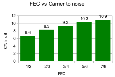
Carrier to noise performance for QPSK as publish in the Intelsat tables.
Digital modulation systems:
The type of modulation system used is dictated by the form of propagation that is used. This is why there is large range of narrow band digital mode out there you can run on your computer. Each digital mode is design to work under certain proportional conditions, therefore the modulation systems are very closely link to propagation. Is also applies to DATV there is two modulation systems that have be designed to work across free space there are: DVB-T/T2 and DVB-S/S2. Where by DVB-T/T2 uses a COFDM as it modulation and because of this it has very good immunity to multipath. The DVB-S/S2 (QPSK/8PSK) format is design as an up and down linking for Satellite broadcasting services. For example if you look at a modulation system like DVB-C (J83a, b or c) this form of modulation system is designed to propagate through cable, such as coaxial and fiber optic. Therefore this mode will perform poorly across free space, where by QPSK is a good all round compromise for DATV use.
The ATSC system is a very good example on how not to do things. This system is based on AM and therefore has all the problems that analog Television had with poor carrier to noise and poor multipathing performance. Just take a look a the graph above showing picture points vs carrier to noise. No matter how much FEC and other forms of error correction you add in, if the underlying modulation system is poor it's not going do much. Because of this at some point in the future Canada and the US will need to go through a second digital change over.
Carrier to noise performance for QPSK as publish in the Intelsat tables.
This is only haft of the information you need to know the other is the noise floor at the receiver end. This is affected by the IF bandwidth being used, in short wider the band width higher the noise floor. When you take this into account with QPSK I found you end up with a more of a bell curve, where by a FEC of 3/4 is the optimal for performance (C/N, error correction and IF bandwidth).
ATV Repeater design and configuration:
The key to getting the best performance out any ATV repeater is to receive the best carrier to noise possible. Therefore it's important to design the repeater around the receiver on the understanding that this will minimize the amount of noise been retransmitted.
The factors that need to taken into account are:
1/ modulation system used
2/ free space path loss
3/ aerial gain
4/ TX power
5/ RX noise floor
6/ Isolation from unwanted narrow band carries and other forms of interference
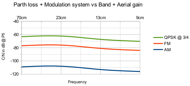
When piloting all this in to a graphical form you soon find out that there is very little difference between 70cm and 23cm bands. Mainly due to higher aerial gain and similar RF output power on both of these bands. I notices this when we lost our 70cm band here back in 2003, found that we had far better over all receive performance on 23cm. The major improvement come about when we made the change over from AM/VSB to FM.
Putting all these factors into account you get something that looks like this:
ATV Repeater design and configuration:
The key to getting the best performance out any ATV repeater is to receive the best carrier to noise possible. Therefore it's important to design the repeater around the receiver on the understanding that this will minimize the amount of noise been retransmitted.
The factors that need to taken into account are:
1/ modulation system used
2/ free space path loss
3/ aerial gain
4/ TX power
5/ RX noise floor
6/ Isolation from unwanted narrow band carries and other forms of interference
When piloting all this in to a graphical form you soon find out that there is very little difference between 70cm and 23cm bands. Mainly due to higher aerial gain and similar RF output power on both of these bands. I notices this when we lost our 70cm band here back in 2003, found that we had far better over all receive performance on 23cm. The major improvement come about when we made the change over from AM/VSB to FM.
Putting all these factors into account you get something that looks like this:
Band
70cm
23cm
13cm
9cm
|
Frequency
435 MHz
1285 MHz
2380 MHz
3380 MHz
|
TX Aerial gain
12dBi
18dBi
22dBi
25dBi
|
RX Aerial gain
6dBi
12dBi
14dBi
14dBi
|
RF power
50W
30W
10W
5W
|
Over a distance of 50km with a -100dB RX noise floor
Aerial design for home station and repeater configurations:
Bands
70/60cm
23cm
13cm
9cm
|
Types of aerials used
Colinear, Log Periodic, Log Periodic Yagi, Quad, Yagi
Colinear, Bi Quad, Quad, Loop Yagi, Yagi, Alfead slot
Bi Quad, Loop Yagi, Alfead slot
Horn, Periodic (Dish), Loop Yagi, Alfead slot
|
Repeater end; wide coverage patten is required this is where staked dipoles are used to provide the gain, where by Alford Slot, broad side colinear or Bi Quad designs are used. With receive panels facing in difference directions this is where you need some form switching to select the required RX panel. With TX panels they can be phased together through standard power devider.
Home station; is unlike repeater aerial system this is where you need to use the highest gain possible. On 70cm high gain Yagis this changes up on 23 and 13cm bands with the use of loop Yagis. Coax loss needs to be kept low as possible, I go by the 3dB rule (no more then 3dB of loss). With cross band ATV repeaters this done with two high gain aerials on each band, one for receive and the other for transmit.
Look through; is where you are able see your returning vision and sound back through the repeater. This is a very useful tool to align your transmitter with. This is where the cross band repeaters have an advantage, you only need minimal filtering at the home station.
Receiver isolation:
At a repeater sites it's important to engineer narrow band carriers around ATV receive inputs. This is because wide band receivers can be made useless with a poorly planed narrow carries near by!
Guide to engineer ATV inputs:
1/ Try and make sure that there is no narrow band TX carries at the same site within the same band. If there are two sites nearby, place ATV receiver at one and place the narrow band TX carries at the other site.
2/ Use high grade coaxial cable like heliax or well screened RG-6/RG-11 cable.
3/ Make sure every thing is earth bonded to a common ground, switch mode power supplies are a major problem at repeater sites they can become noise generators.
4/ Always use horizontal polarization where possible, helps when working around narrow-band transmissions on vertical.
5/ Receiver filters are always a must for TV tuners they are wide band and can be overloaded very easily
Transmitter design:
Very important to make sure that audio and video levels are set correctly and any distortion of the video waveform can be a problem when reception of the repeater is poor. Linear amplifiers, driver and power stages need be operating within there linear zones! If not this will course inter-modulation and could affect the receiver performance. When using output filtering between the power amplifier and the aerial system. Always place a circulator before the filter and after the PA stage. This way the power amplifier will see a 50 ohm match across it's operating frequency.
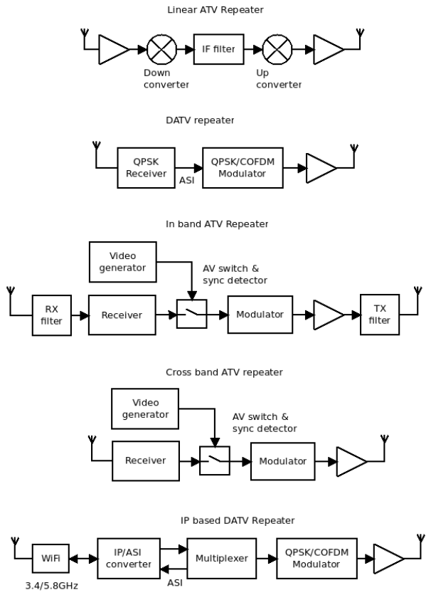
Types of ATV repeaters:
Linear ATV Repeater; mixes down the received signal to an IF frequency and then remixes back to RF on another frequency. With this kind of repeater you can operate any modulation system within the pass band of this repeater. There is no demodulator nor modulator in this type of configuration.
Digital ATV repeater; is like a Linear ATV Repeater where by you have a QPSK receiver demodulating to a transport stream ready to be remodulated again, this could at the ASI or IP levels. Another way to look at these types of repeater is as bent pipe, what goes in comes out.
In band ATV Repeater; this is where both receiver and transmitter are both in the same band, like most voice repeaters are. There are two problems with these repeater is that you need very good filtering requirements to get this configuration to work well. The other is the home station need same level of filtering to remove their TX signal from what is being received.
Cross band ATV repeater; Are the most common type used world wide for good reason, they provide the best all round performance. Both the in band and cross band repeater have two modes of operation, one repeat and the other beacon mode. The switching between modes is done through a sync detector this basically a PLL that locks to line frequency of the received video. The switch in many cases is nothing more then standard change over relay for the audio and video. In beacon mode this where ATV repeaters display their callsigns and other information; like, club meeting, about the repeater, events, contact information and so on. Device used for beacon mode can be, electronic picture frames, Teletext generates, computer displays and so (anything that has a video output can be used).
IP based DATV Repeater; again cross band repeater configuration where by you have transmitted and received digital video via IP. This is normally done on 9 and 5cm bands with modified high speed WiFi equipment. With a QPSK or COFDM output relaying the received IP streaming video, these type of repeaters are both an ATV and a hight speed data repeaters in one.
Home station; is unlike repeater aerial system this is where you need to use the highest gain possible. On 70cm high gain Yagis this changes up on 23 and 13cm bands with the use of loop Yagis. Coax loss needs to be kept low as possible, I go by the 3dB rule (no more then 3dB of loss). With cross band ATV repeaters this done with two high gain aerials on each band, one for receive and the other for transmit.
Look through; is where you are able see your returning vision and sound back through the repeater. This is a very useful tool to align your transmitter with. This is where the cross band repeaters have an advantage, you only need minimal filtering at the home station.
Receiver isolation:
At a repeater sites it's important to engineer narrow band carriers around ATV receive inputs. This is because wide band receivers can be made useless with a poorly planed narrow carries near by!
Guide to engineer ATV inputs:
1/ Try and make sure that there is no narrow band TX carries at the same site within the same band. If there are two sites nearby, place ATV receiver at one and place the narrow band TX carries at the other site.
2/ Use high grade coaxial cable like heliax or well screened RG-6/RG-11 cable.
3/ Make sure every thing is earth bonded to a common ground, switch mode power supplies are a major problem at repeater sites they can become noise generators.
4/ Always use horizontal polarization where possible, helps when working around narrow-band transmissions on vertical.
5/ Receiver filters are always a must for TV tuners they are wide band and can be overloaded very easily
Transmitter design:
Very important to make sure that audio and video levels are set correctly and any distortion of the video waveform can be a problem when reception of the repeater is poor. Linear amplifiers, driver and power stages need be operating within there linear zones! If not this will course inter-modulation and could affect the receiver performance. When using output filtering between the power amplifier and the aerial system. Always place a circulator before the filter and after the PA stage. This way the power amplifier will see a 50 ohm match across it's operating frequency.
Types of ATV repeaters:
Linear ATV Repeater; mixes down the received signal to an IF frequency and then remixes back to RF on another frequency. With this kind of repeater you can operate any modulation system within the pass band of this repeater. There is no demodulator nor modulator in this type of configuration.
Digital ATV repeater; is like a Linear ATV Repeater where by you have a QPSK receiver demodulating to a transport stream ready to be remodulated again, this could at the ASI or IP levels. Another way to look at these types of repeater is as bent pipe, what goes in comes out.
In band ATV Repeater; this is where both receiver and transmitter are both in the same band, like most voice repeaters are. There are two problems with these repeater is that you need very good filtering requirements to get this configuration to work well. The other is the home station need same level of filtering to remove their TX signal from what is being received.
Cross band ATV repeater; Are the most common type used world wide for good reason, they provide the best all round performance. Both the in band and cross band repeater have two modes of operation, one repeat and the other beacon mode. The switching between modes is done through a sync detector this basically a PLL that locks to line frequency of the received video. The switch in many cases is nothing more then standard change over relay for the audio and video. In beacon mode this where ATV repeaters display their callsigns and other information; like, club meeting, about the repeater, events, contact information and so on. Device used for beacon mode can be, electronic picture frames, Teletext generates, computer displays and so (anything that has a video output can be used).
IP based DATV Repeater; again cross band repeater configuration where by you have transmitted and received digital video via IP. This is normally done on 9 and 5cm bands with modified high speed WiFi equipment. With a QPSK or COFDM output relaying the received IP streaming video, these type of repeaters are both an ATV and a hight speed data repeaters in one.
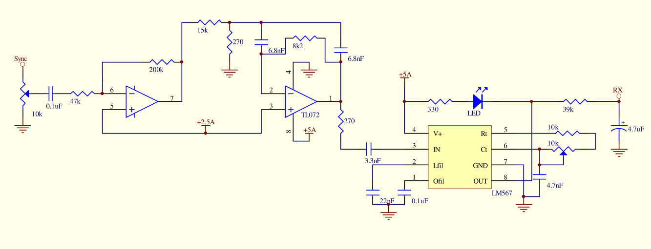
Sync detector:
In the same way that we use sub-tones to open up FM voice repeaters we can use this concept to switch across from beacon mode to repeater operation with an ATV repeater. Where by composite video is made up of many parts, Field sync, line sync, Luminance and Chrominance. With PAL you have a line rate at 15.625kHz and with NTSC at 15.75 kHz, Both line rates are close enough to each other that same circuit layout can be used. This circuit works like this; the TL072 make up a gain stage and a active pass band filter at the line rate frequency. The LM567/NE567 is a PLL tone decoder, when in coming video is present you get lock on the PLL and a logic 0 on the output. This can feed into a micro-controller or control a relay driver to switch over the audio and video.
In the same way that we use sub-tones to open up FM voice repeaters we can use this concept to switch across from beacon mode to repeater operation with an ATV repeater. Where by composite video is made up of many parts, Field sync, line sync, Luminance and Chrominance. With PAL you have a line rate at 15.625kHz and with NTSC at 15.75 kHz, Both line rates are close enough to each other that same circuit layout can be used. This circuit works like this; the TL072 make up a gain stage and a active pass band filter at the line rate frequency. The LM567/NE567 is a PLL tone decoder, when in coming video is present you get lock on the PLL and a logic 0 on the output. This can feed into a micro-controller or control a relay driver to switch over the audio and video.
ATV Controller:
Controlling an ATV repeater requires different approach then what you would use for standard voice repeater. They both used DTMF over a FM voice channel this provide away to communicate to the controller thats about where the stimulatory ends. With an ATV repeater you have switching of multiple audio/video channels, these could be video generators and any number receivers or transmitters. In an ATV configuration you have one main output channel that displays on screen information providing user feedback. Other functions are RX aerial switching, monitoring stat of the sync detectors, monitoring the VSWR of the power amplifiers and be able to remotely shut down the transmitters and/or any receiver inputs. Another possible function is audio pass through to switch to cross link any in coming FM voice channel to be relay out via the repeater sound channels.
Controlling an ATV repeater requires different approach then what you would use for standard voice repeater. They both used DTMF over a FM voice channel this provide away to communicate to the controller thats about where the stimulatory ends. With an ATV repeater you have switching of multiple audio/video channels, these could be video generators and any number receivers or transmitters. In an ATV configuration you have one main output channel that displays on screen information providing user feedback. Other functions are RX aerial switching, monitoring stat of the sync detectors, monitoring the VSWR of the power amplifiers and be able to remotely shut down the transmitters and/or any receiver inputs. Another possible function is audio pass through to switch to cross link any in coming FM voice channel to be relay out via the repeater sound channels.