PIC Colour bar pattern generator
Background:
Video test equipment has been used as long as there has video been around. You need away to a line up cameras, Television transmitters and set video levels, this where this gear comes into use.
Introduction:
I needed to find away to build a portable video test source, so I started to look around for IC's that would do this job. I could not find anything that was suitable so I ended up thinking how I could put one together, maybe logic gates or an EPROM? Then I had a closer look at what I could get a Micro-controller to do. All video is, is nothing more then a stepped waveform. Sync could be made up out of logic 1 or a 0 it's all comes down to what you could do with the timing. I started out with a PIC16F628A but I could not get this PIC chip to work within this circuit configuration until I moved to the PIC16F84A. With this chip I had eight logic outputs on port B to make use of, this is why I decided to go with the two bit colour. Likewise I also had five pins left on port A, so I made one the sync output and the remaining four as BCD inputs. I ended up with three IC's one being the 5 volt regulator, as you can see there is very little involved within this circuit.
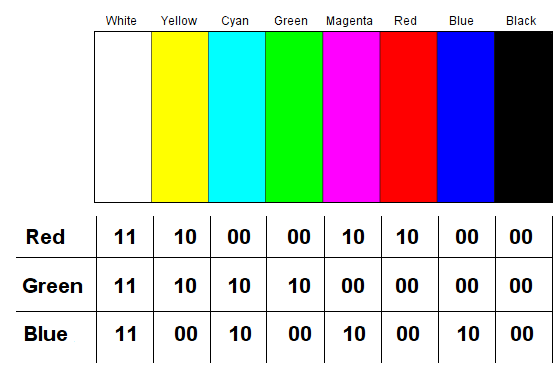
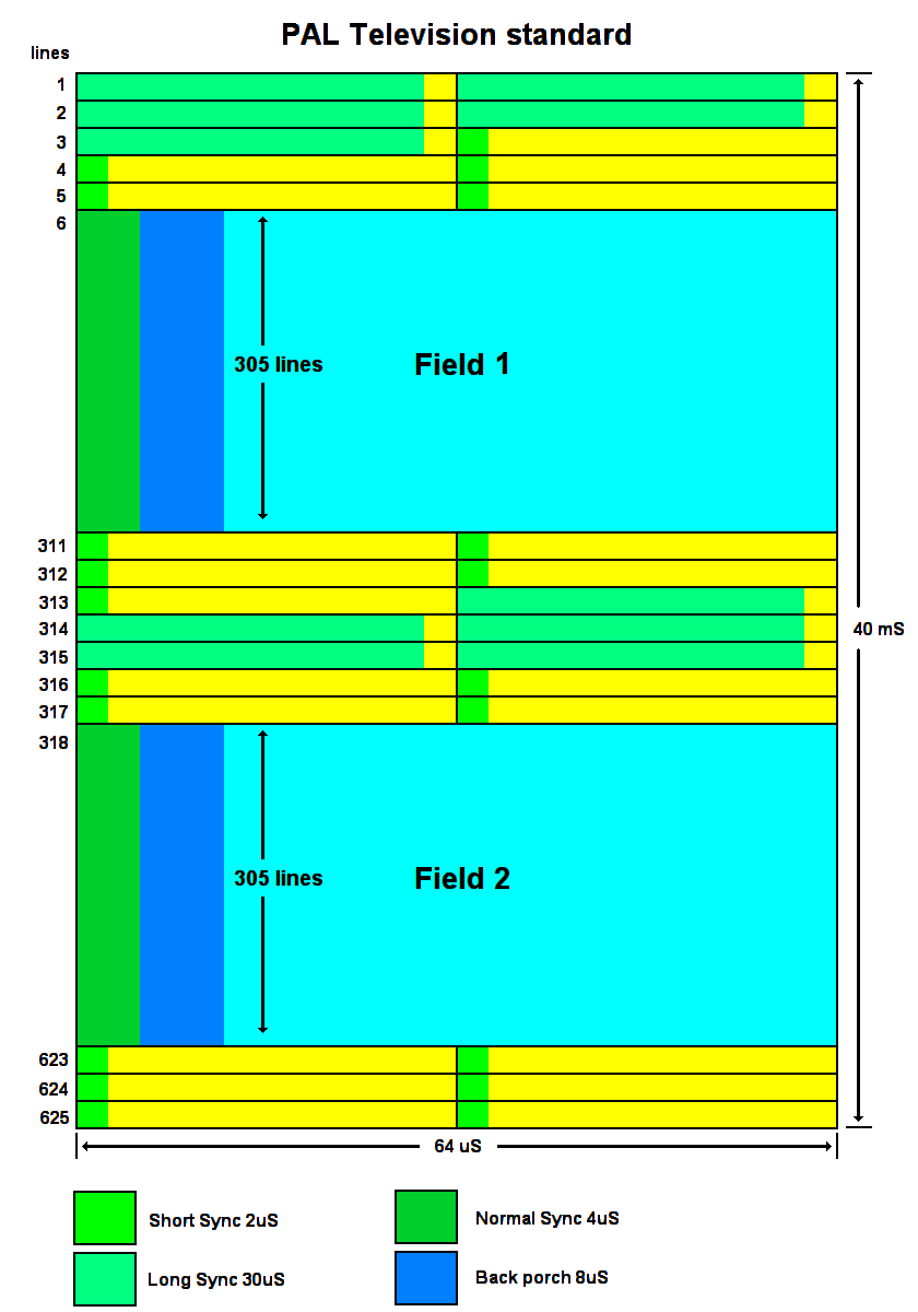
The colour encoding works by converting RGB (Red, Green, Blue) to phased modulated C (Chrominance) as a sub carrier. This works by having a colour burst this sets up the phase reference for that line, in PAL (Phase Alternate Line) TV system this is flip by 180° on each line. This has the advantage of off setting any unwanted colour phase shift. This has always been a problem that affected the NTSC system. The second signal is the Y (Luminance) this sets brightness level and provides the monochrome picture information. It is very important to have the encoding side levels set for one volt pack to pack into a 75 ohm load. To a line video equipment you need to start with a known reference other wise you end up going around in circles and getting no where.
Features:
1/ Small size
2/ 2 bit RGB colour
3/ Low cost simple to build
4/ 16 Patterns
5/ Can be battery powered
Specifications:
PAL-B,G,I
S-video and composite video
1 volt P to P into a 75 ohm load
Video test equipment has been used as long as there has video been around. You need away to a line up cameras, Television transmitters and set video levels, this where this gear comes into use.
Introduction:
I needed to find away to build a portable video test source, so I started to look around for IC's that would do this job. I could not find anything that was suitable so I ended up thinking how I could put one together, maybe logic gates or an EPROM? Then I had a closer look at what I could get a Micro-controller to do. All video is, is nothing more then a stepped waveform. Sync could be made up out of logic 1 or a 0 it's all comes down to what you could do with the timing. I started out with a PIC16F628A but I could not get this PIC chip to work within this circuit configuration until I moved to the PIC16F84A. With this chip I had eight logic outputs on port B to make use of, this is why I decided to go with the two bit colour. Likewise I also had five pins left on port A, so I made one the sync output and the remaining four as BCD inputs. I ended up with three IC's one being the 5 volt regulator, as you can see there is very little involved within this circuit.
The colour encoding works by converting RGB (Red, Green, Blue) to phased modulated C (Chrominance) as a sub carrier. This works by having a colour burst this sets up the phase reference for that line, in PAL (Phase Alternate Line) TV system this is flip by 180° on each line. This has the advantage of off setting any unwanted colour phase shift. This has always been a problem that affected the NTSC system. The second signal is the Y (Luminance) this sets brightness level and provides the monochrome picture information. It is very important to have the encoding side levels set for one volt pack to pack into a 75 ohm load. To a line video equipment you need to start with a known reference other wise you end up going around in circles and getting no where.
Features:
1/ Small size
2/ 2 bit RGB colour
3/ Low cost simple to build
4/ 16 Patterns
5/ Can be battery powered
Specifications:
PAL-B,G,I
S-video and composite video
1 volt P to P into a 75 ohm load
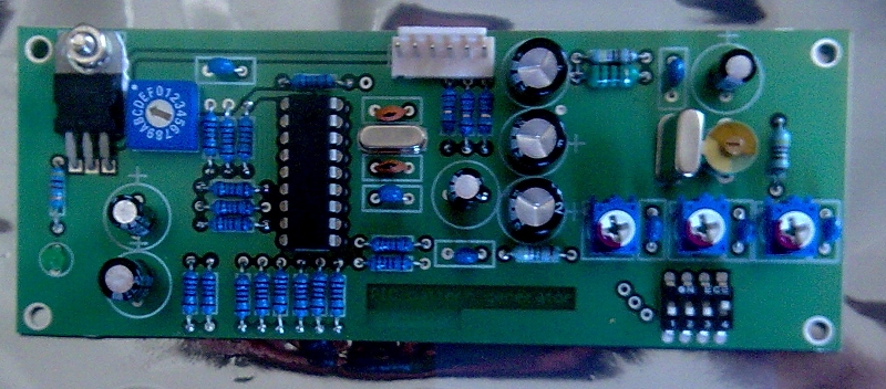
Circuit description:
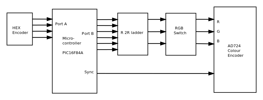
This pattern generator is based on IC1 the PIC16F84A micro-controller with port B set as RGB drive via R 2R ladder network this is made up with 1k resistors. The micro-controller timing is set by a 20 MHz crystal. Port A is the Hex inputs for pattern switching from EN1 (HEX encoder) as well as the sync output drive on pin one. It took all of the 2k memory space to write the code for this project. The hardest part was getting the timing right for the equalizing pulses in the blanking interval. The speed of the Micro-controller also limited what I could do in way of test patterns, my switching time was no more then about fourteen times within 52uS window, the visible part of the waveform. The outputs from port B are feed via S1 a four way switch (for RGB switching) this can turn on or off each part of RGB levels as required, where by the last position is the PAL/NTSC chrominance switch. VR1, VR2 and VR3 are the drive level adjustments. To a line these presets you select pattern four (white block), set for one volt pack to pack and to null out the chrominance.
IC2 the AD724 colour encoder is referenced from 4 x clock at 17.73448 MHz or 1 x at 4.4336 by setting JP1 to ground. The good thing about this encoder is there is no need for a delay line and requires minimal components. The out putted video is able drive into a 75 ohm load on both outputs the composite and the Y/C (S-video). By connecting the composite and the Y output to a common switch you are able turn the colour on or off.
Test card numbers in Hex
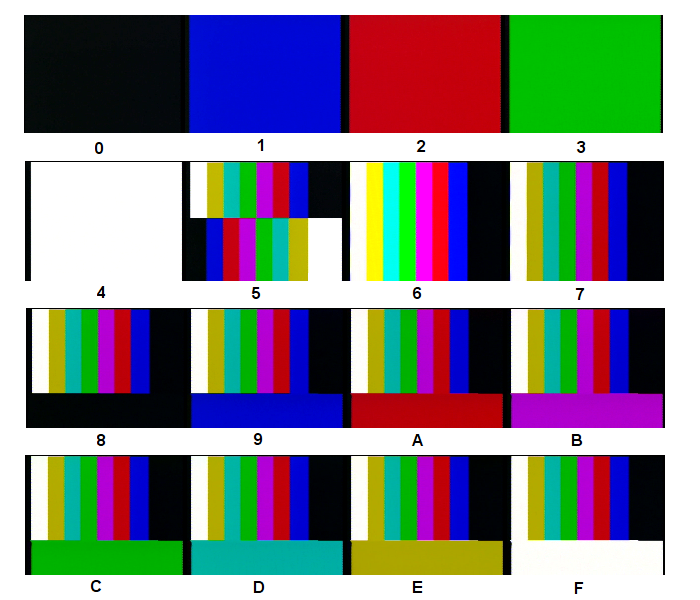
0/ Black level
1/ Blue raster
2/ Red raster
3/ Green raster
|
4/ 100% white
5/ Transition bars
6/ 100% colour bars
7/ 75% colour bars
|
8/ Black bar
9/ Blue bar
A/ Red bar
B/ Magenta bar
|
C/ Green bar
D/ Cyan bar
E/ Yellow bar
F/ White bar
|
This pattern generator will provide you an indication to where the levels are, it's not a replacement for professional test equipment. But as a small compact portable signal generator it works well.
Board overlay