FM ATV Receiver
FM ATV Receiver
FM ATV Receiver
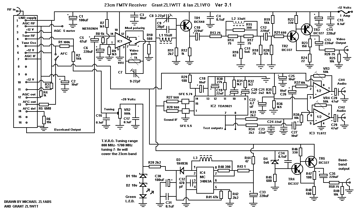
This receiver is based around the use of a TVRO tuner head. These are used in many types of analogue satellite receivers. The TVRO tuner has an IF input tuning range of about 800 MHz to 1800 MHz. The IF input can also be used to give a DC out supply to feed a LNB or antenna pre-amp and the output provides a baseband signal. As you can see, the tuning range of 800-1800 MHz will easily cover the 23 cm band. To pickup FM ATV signals you may need to use one or possibly two low noise preamps at the front end with a reasonably high gain aerial.
RX Circuit description:
The TVRO takes the incoming RF and mixers it down to an IF of 480 MHz, with a bandwidth of about 25MHz. This is then coupled into the demodulater half of the TVRO module, which provides the baseband. Pin 1 is the dc supply for the F-socket (IF in). Pins 2 and 7 are the AGC in and pin 12 is AGC out. 12 volt supply is on pins 3, 6, and 10 and also pin 11 via an 82 ohm resistor. For tuning (VR1) is a 10-turn pot. Range is 0 to 20 volts on pin 4. Pins 5 and 13 are AFC and 14 is AFC defeat.
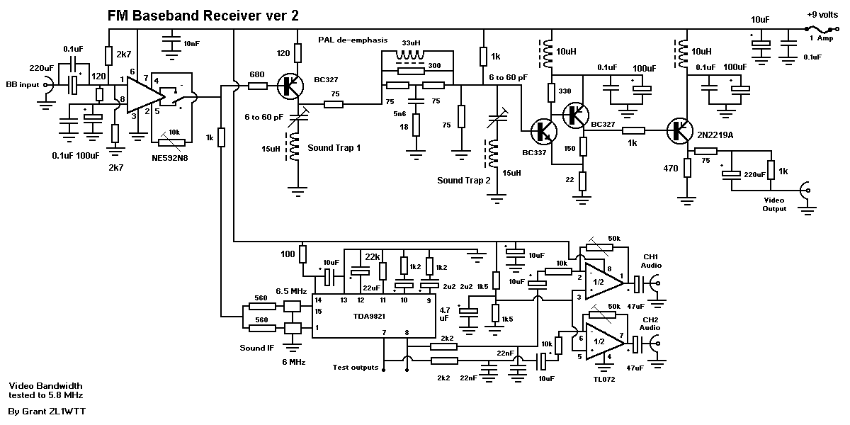
IC1 The incoming baseband signal is feed into pin 14 of the NE592. VR2 sets up the video gain and VR3 adjusts the HF boost response. Either of the amplifier output pins 7 and 8 can be selected by the positive/negative modulation switch, depending on the polarity of modulation you wish to receive. The output of the NE592 is then spit two ways. One feeds the video output transistors, via the video de-emphasis network. The second feed is passed via ceramic filters to the sound demodulators contained in IC2.
The video output stages consist of transisors TR1, TR2 and TR3 and associated componentry. The emitter of TR1 (BC548) has a tuned circuit, that acts as a sound IF trap. The output from the transistor is then coupled into a CCIR standard video de-emphasis network which is matched for 75 ohm impedance in and out. The 75 ohm and 300 ohm resistors used can be a pair of 150 ohm resistors wired in parallel or series as required, or if obtainable, single resistors of the required value may be used. A standard feedback pair is used on the video output stage TR2, TR3 (BC337, BC327). The video is fed into the base of TR2 which then drives TR3. The signal comes off the collector of TR3 providing the video output.
IC2 is the TDA9821 dual PLL sound demodulater. This takes the outgoing signal from the NE592 through the 5.5 and 5.742 MHz ceramic filters which then feeds the two inputs of IC2 pins 1 and 15. The audio gain has been set by the use of the two 1.2k resistors and the two 2.2 uF caps. The audio output pins 7 and 8 are connected to the sound de-emphasis networks.
IC3 is a TL072 op-amp used as a dual channel line amp. The pins 2 and 6 are the two inputs. The audio gain is set by VR4 and VR5. The output pins 1 and 7 are coupled to the outputs which then provide the two audio output channels.
Optional extras not shown include a buffered baseband output from the TVRO module for use with data or other wideband experiments, and a stabilised voltage booster / regulator section for the tuning voltage, which would be required for portable work, or elsewhere where slowly discharging batteries are used.
(C) 1998 ZL1WTT ZL1VFO
Boards based on this article will be avaliable from Wayne ZL1UJK.
Updated base band receiver circuit
With older analog Satellite receivers coming harder to find, there is an increasing need for a simple FMTV receiver design. This is why I have rework old 23cm circuit and have come with these changes. At the moment I am looking around for L-Band (950 to 2150Mhz) tuner modules that would meet the requirements for ATV. The features I am looking for are these PLL controlled with ability to voltage turned if required, narrow band filtering and a base-band output.