GaAS FET Bias circuits
GaAS FET Bias circuits
|
The self-biasing circuit uses a PNP transistor (BC558). The circuit needs both positive and negative voltages as per the diagram. To work out the value of Rd, you need know the GaAs FET's DC operating parameters. Data below |

|
FETs that were used.
Where Rd = Vdd / Id
EPA018A Rd = 5v / 55 mA = 90 ohms
EPA060B Rd = 5v / 180 mA = 27 ohms
| Idss | Vp | Vds | NF | P out | G dB | ||
| EPA018A-70 | 55 mA | -1v | 3v | 0.75 | 20 dBm | 11 dB | |
| EPA060B-70 | 180 mA | -1v | 3v | 1.4 | 26 dBm | 9 dB |

Simple amplifier for 0.03 to 4 GHz
|
The gali 4 amplifier is made from the Waikato VHF groups prototyping board. Using two DSE PCB mount SMA sockets for the RF input and outputs. The 13.8 volts DC is feed via a 1nF feed-though capacitor to the 7808 regulator. And by looking at the Mini-circuits web site, the bias configuration for 8 volts is 52 ohms. This is made up from two SMD resistors with a value of 100 ohms each. Both 1nF capacitors that are on pins 1 & 3 of the Gali-4 are SMD type. The case is made up from strips of tin plate soldered to edge of the prototyping board.
|
|

|
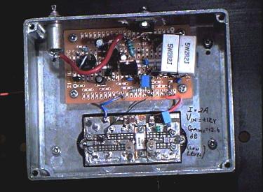
Three stage 23cm amplifier
|
Stages 1 & 2 use a similar bias circuit layout. LM78L05 regulates to a 5 volt input to the negative volts generator (7660). The 7660 provide negative volts for both bias circuits at -5. The class A PNP transistor circuit is common to all the amplifier stages. Bias conditions were calculated out for the power GaAs FETs that is used. There is two equations used to calculating components for different bias conditions. |

|
|
For the Stage 3 the power amplifier I needed to add in voltage protection for this circuit. The expense of the power GaAs FET used required extra components fitted to protect this device. The NE555 oscillator is connected to two transistors BC337, BC327 (NPN, PNP). The output is then rectified via the two diodes as well as the 10uF capacitors. The LM79L05 regulator provides the negative five volts. The IRF4905 P-channel power MOSFET is tuned on when there is -5 volts present on the output of the LM79L05 regulator. There for there is no current provided to the drain of the GaAs FET when there is no negative bias on the gate. And again a class A bias circuit is used for this device. SMA connectors were used for the RF input and output. Which are fitted on to 50ohm lines. The trim-capacitors were used to tune out the internal reactance of the device. |
|
|
The photo is of the 10 watt 23cm PA
| 3 Stage 10 watt Amplifier | ||
| +12 volts supply, 2 tone test @ 1MHz spacing | ||
| Power level out in dBm | IMD level below individal tones (dBc) | Comments |
| 30 (1 watt) | -62 | Used for digital DVB |
| 35.7 (3.7 watts) | -50 | Used for digital DVB |
| 37.7 (6 watts) | -40 | Used for digital DVB |
| 39.3 (8.5 watts) | -28 | Used for analog FM or SSB |
2.3 GHz down converter
|
I have become interested in 13cm band and possibility of using the lower part of this band for an ATV repeater output. The problem with this band it has become unusable at top end due to spread-spectrum devices and Microwave ovens and so on.By experimenting in lower part of this band I have found ATV is very doable. Working with modified Wifi equipment such as amplifiers and aerials. I found using analog FM and QPSK (DVB-S) digital modulation all worked well, I have had next to no problems operating just above 2.3GHz. This band is very easy to receive as you can see a S-band LNB’s already cover this frequency range. The next step is to design and build an Alford slot wave guide antenna. LD- MOS power amplifiers are also available up to 100 watts. The problem is finding useable UHF spectrum to experiment with. 2.4GHz Bi-Quad dish feed made up from brazing wire and 10mm brass tubing. The ¼ wave balun is soldered to a N-socket mounted on the back of Aluminium plate. The dialectic came out of a off cut of RG-213 coaxial cable, giving me a Velocity factor 0.66. |
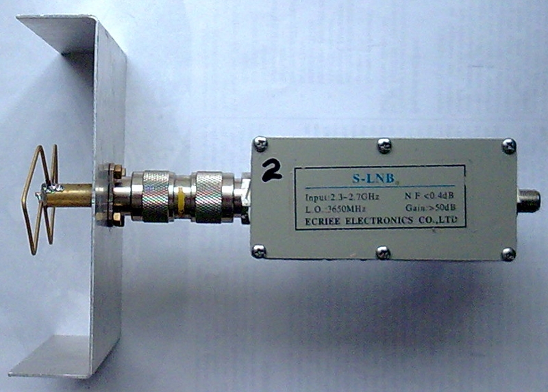
S-band LNB test receiver with 2.4GHz Bi-Quad dish feed for the aerial. |
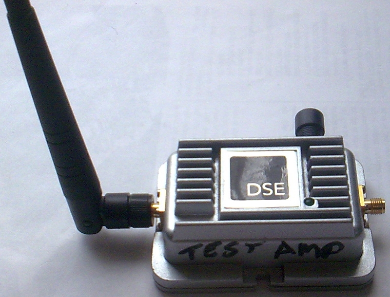
Test Wifi amplifier with a standard antenna. |
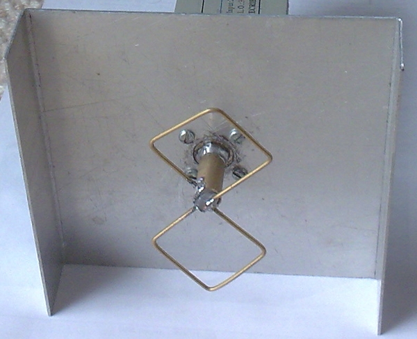
Bi-Quad dish feed |
3.3 GHz up converter
Local Oscillator / Multipliers

|
23cm to 9cm Transposer The 9cm band has a lot of potential for ATV usage. At this time does not have the interference problems of the 13 cm band (2.4 GHz). One of the newer projects I am work on, is a linear up converter. Using a VK5EME / ZL1SWW oscillator multiplier board. The multiplier output frequency could be for example 2.1 GHz. IF in of Whitford on 1248 MHz + LO 2.1GHz = 3.348 GHz (9cm band) RF out. The Mixer is a mini circuits SKY-42 SMD mount. The Mixer output has a two-pole interdigital filter. Followed by an ERA * amplifier device. |
|
New 9cm up converter This TX up converter has been designed with an IF input frequency range of 1.2 to 1.3 GHz. The local oscillator made up from a programmable VCO. Which has a settable range of 1.9 to 2.3 GHz in one MHz steps. The mixer output is filtered to remove the unwanted image. The ERA-5 amplifier, outputs about 8 mW of RF. This up converter work well with both digital QPSK (DVB-S) and analog FM. The RX converter is a C band LNB that is connected to a Digital / Analog receiver. |
|

Photo 1 is of the 2.1 GHz VCO. |
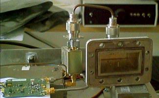
Photo 2 is of the up comverter. |
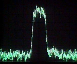
Photo 3 is of the Spectrum Analyzer showing the digital TV signal at 3.382 GHz. |
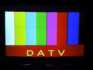
Photo 4 is of the receiver showing the receved TV signal. |
10 GHz up converter

The block diagram right shows the up-converter layout using the power GaAs FETs from above. One problem is where does one find 9 GHz DROs? By changing the location and adding a non-metallic spacer, the resonant frequency of the DRO (Dielectric Resonant Oscillator) can be changed. By adjusting the IF frequency, you can alter the RF output frequency. From measurements that I have made of the RF output, I have estimated about +10 dBm (10mW) between 10-11 GHz. With the addition of an aerial, 15 to 27 dBi gain can be expected. Photo is of the 10 GHz up converter |

|

|
The 3 cm band has a bandwidth of 500 MHz (10 to 10.5 GHz). Therefore multiple TV channels can be sent on one RF link by adding more than one modulator into the IF of the upconverter. This why I am interested in this band. For this to work the converter must be kept linear. |
|
The bandwidth limit is a maximum of 500 MHz |
For example I have mixed up the IF from my KU LMB to fit inside the 10 GHz band. By measuring the bit error rate I can check my linearity across the link. Below is photo of my Spectrum Analyzer showing the IF of Optus B1.

|
|
|
You could also use the same idea for mixing up from the IF of a C band LMB to send out on the KU band.
|