 Bands vs aerials used

| Bands |
Freqency range |
Types of aerials used |
| 50cm |
614 to 622 MHz |
Colinear, Log Periodic, Log Periodic Yagi, Quad, Yagi |
| 23cm |
1.24 to 1.3 GHz |
Colinear, Quad, Loop Yagi, Yagi |
| 13cm |
2.396 to 2.45 GHz |
Bi Quad, Loop Yagi |
| 9cm |
3.3 to 3.5 GHz |
Horn, Periodic (Dish), Loop Yagi |
| 5cm |
5.65 to 5.85 GHz |
Horn, Periodic (Dish) |
| 3cm |
10 to 10.5 GHz |
Horn, Periodic (Dish) |
Colinear aerial design
For UHF bands 50 & 32
Colinear aerial
| Bands |
A |
B |
C |
D |
E |
F |
G |
Total length |
| 50cm |
473mm |
111mm |
157mm |
236mm |
238mm |
46mm |
31mm |
2.158m |
| 32cm |
315mm |
74mm |
104mm |
157mm |
159mm |
31mm |
21mm |
1.435m |
Return loss measurements of the colinear design - subtract 17 dB from the Return loss displayed. At 615 MHz (50 cm band) the Return loss is 27 dB, or SWR of 1.1 at this frequency.
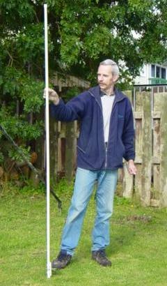
Photo of Harry ZL1BK with a 50 cm band colinear
Construction notes
Sections A and C (x4) are made from brass tubing 10mm OD x 8mm ID. The brass tubing length given in the table (right hand column) should include an additional cutting allowance when ordering.
The center of the colinear is constructed from a length of RG-213, which has had the outer cover and braid removed. The total RG-213 length is a guide - add enough to solder the center conductor into the N connector.
The shorted stub G is made from RG-178. A slot is cut into the tube A at length F from end of tube, and the centre conductor of the stub is soldered onto the centre of the RG-213, and the shield to the brass A.
The brass tubes should be crimped top and bottom (onto the RG-213) with a hex crimping tool to hold them in position.
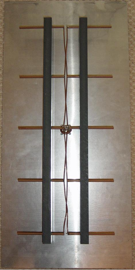
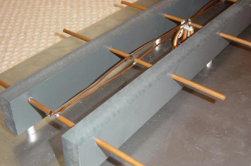
50cm Bi-Quad Repeater layout
ATV projects
There are those who think ATV is dead, but this attitude could not be further away from the truth. With the new digital technology coming available opens new possibilities for the hobby. There is so many areas in ham radio today, where we are still using outdated equipment and ideas. ATV as well as Digital modes are using state of the art thinking and technology!
Current projects; The next generation of ATV repeaters
1/ With this new digital upgrade the Auckland ATV group will have four video channels in the DVB multiplex. As well as spare inputs for video, text information and other types of video inputs.
2/ The new ATV 8x8 video/audio switcher with video overlay and sync detectors. This will be at heart of new digital repeater layout, giving the ability to switch any input to any output. This unit interconnect with as many as eight mpeg encoders in a multiplex.
3/ The new 50cm Aerial design that I have been working on in my spare time. Using four Bi-quads placed on two panels off set by 90º for improved aerial gain. The modelling was done on the 4nec software that Andrew ZL2ALW demo at VHF convention over Easter.
Here is what I have come up with for an aerial up grade.
I started out by first shifting the 23cm full wave panel design to the 50cm band, but the patten that I got was not wide enough. So then I tried staked dipoles, but this did not give a lot of gain for area I had to work with. This is when I began to look at Bi-quads designs using full wave loops. This diagram below shows the aerial system modelled on the current frame work at the Auckland ATV repeater site.
This is the plot of this design in the Horizontal plane, the maxim gain is 15 dBi. With the power been divided four ways, the gain becomes 9 dBi. This is still a lot power ERP from this set up, 100w in 800w ERP out.
Frequency Plot from 515 to 715MHz, as you can see the return loss is 30dB at 615MHz.
23cm broad side colinear aerial
This aerial is made from ten-half wave elements with a PVC insulator at the current point. The reflector is made out of two-millimetre thick aluminium panel. There are six-holes drilled into the back panel to fit six M6x40mm bolts through in to the PVC. One millimetre diameter copper wire to interconnect the copper elements. All of the elements are spaced 45mm from the back panel. A panel-mount N socket is mounted into back plate at the central point. U-balun and feed are made using RG-142 coax with a velocity factor of 0.695.
Return loss measurements
Mkr 1: 1251MHz -12.7dB
Mkr 2: 1280MHz -33.0dB
23cm Yagi
The 23cm yagi design was made for the frequency range 1240 to 1300 MHz. This is used in Auckland area for receiving ATV on 23cm.
The yagi looks like a small UHF Television aerial when it's mounted.