Apple II/II+/IIe IDE Drive Interface
The following document describes the current status of an IDE Drive Interface for the Apple II/II+/IIe.
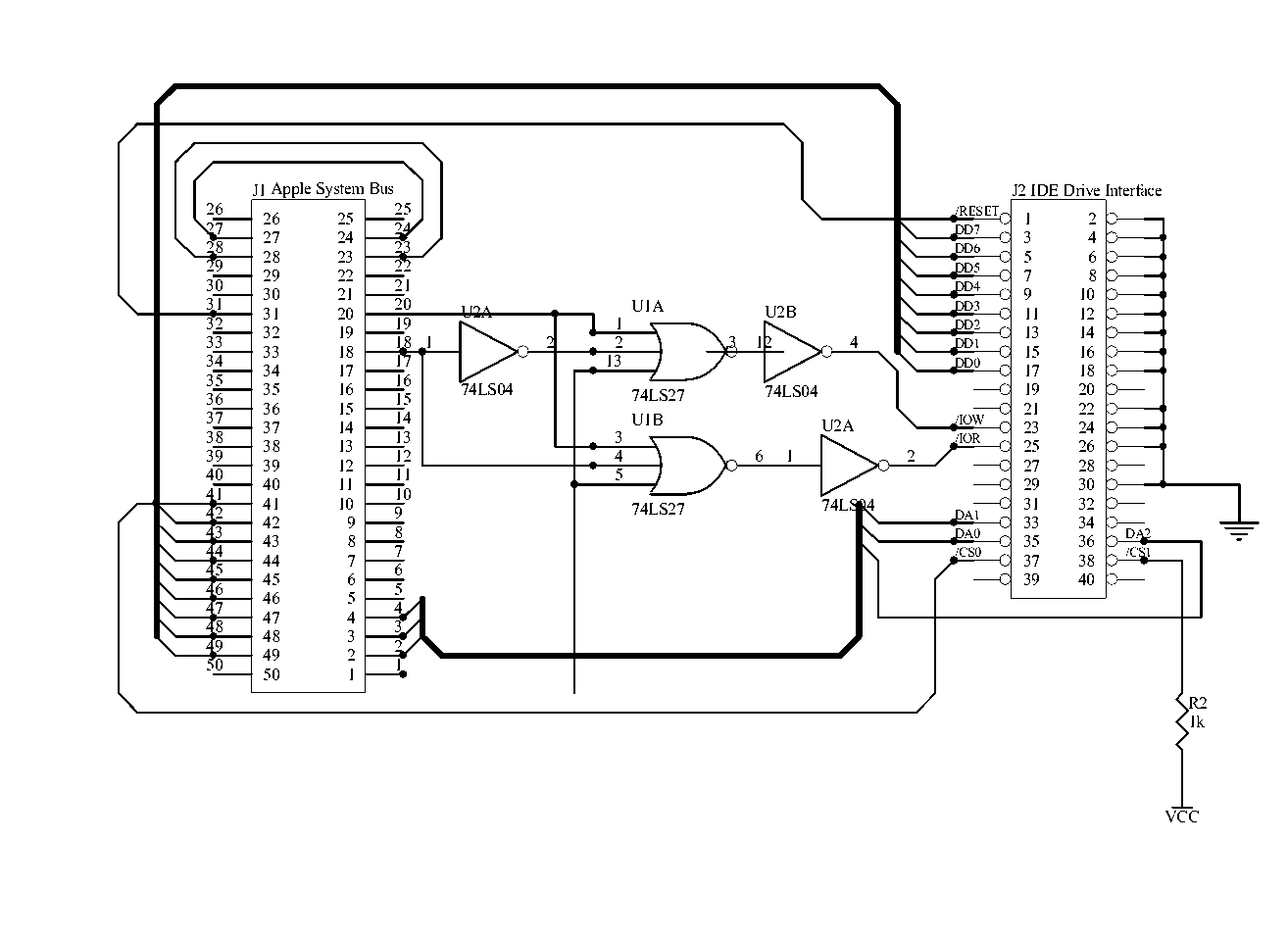
The project is not complete. The interface shown here allows the IDE Drive registers to be accessed from the Apple II. The outstanding item is the completion of the required EPROM so ProDOS recognizes the card as a block device. Work on this EPROM is currently in progress.
Features of this interface are:
Things still to be done:
Building the Interface:
Interface Parts List
| DigiKey | Jaycar | Description | Qty |
| DM74LS04M-ND | ZS-5004 | U3 74LS04 Hex Inverter | 1 |
| DM74LS27N-ND | ZS-5027 | U2 74LS27 Triple 3 Input NOR Gate | 1 |
| P4849-ND | RC-5490 | 0.1uf Monolithic Capacitors | 3 |
| 1.0XBK-ND | RR-0572 | 1K0 1/2W Metal Film Resistors | 1 |
| MHB40K-ND | PP-1114 | 40 Pin IDC Vertical Header | 1 |
| MHB50K-ND | PP-1115 | 50 Pin IDC Vertical Header | 1 |
Power Supply Parts List (not shown in schematic)
| DigiKey | Jaycar | Description | Qty |
| ZV-1505 | 7805 +5v Fixed Regulator | 1 | |
| P5183-ND | RE-6180 | 220uf 50v Electrolytic Capacitor | 1 |
| P5134-ND | RE-6066 | 10uf 16v Electrolytic Capacitor | 1 |
Apple II System Bus Attachment Cable (not shown in schematic)
| DigiKey | Jaycar | Description | Qty |
| PS-0990 | 50 Pin IDC Line Socket | 1 | |
| 50 Pin IDC Edge Connector with adaptor to Apple II System Bus | 1 | ||
| WM-4508 | 50 Way IDC Ribbon Cable | 1 |
Notes:
Frequently Asked Questions
How does the IDE interface tell if the Apple is talking to it?
The Apple II unlike the TRS-80 doesn't require the same level of address decoding because the Device Select and I/O Select lines are enabled for a specific slot only when the memory address range for that slot is selected ($CnXX for I/O Select and $C0nX (n=slot+8).This means that the unlike the IBM PC architecture where a card will have the same memory and port addresses regardless of the slot they are plugged into the memory addresses of an Apple card change based on the slot.
Device Select (Pin 41 on the Apple bus) is connected to the IDE interface "enable" pin.
The IDE enable pin is Pin 37 on the IDE connector (/CS0)
How does the IDE drive know which address you are trying to read?
For the purposes of what we are doing the IDE drive has 8 registers.The various other gates in the circuit are used to convert the Apple bus R/W line into the separate /IOR and /IOW lines required by the drive as follows:The register address is controlled by the DA0/DA1/DA2 pins on the IDE connector. Notice how these are tied to the A0,A1,A2 lines on the Apple address bus. The drive will only use the data on DA0/DA1/DA2 if /CS1 is low which is tied to the apple Device Select line.
If the interface was connected to slot 7 by accessing memory addresses $C0F0..$C0F7 we can read and write the IDE drive registers and pass data via the data bus.
The following pins on the Apple bus are used:
To derive the IDE /IOR signal the following occurs.
The following signals will exist on the Apple bus:
- Pin 18 High
- Pin 20 Low
- Pin 41 Low
Pin 18 is passed through the inverter U2A to convert from high to low. The output of inverter U2A and Pin 20 and Pin 41 pass through U1A and if all are low then the output of U1A is high. The output of U1A is passed through the inverter U2B and connected to IDE Pin 25 /IOR.
To derive the IDE /IOW signal the following occurs.
The following signals will exist on the Apple bus:
- Pin 18 Low
- Pin 20 Low
- Pin 41 Low
Pin 18 and Pin 20 and Pin 41 pass through U1B and if all are low then the output of U1B is high. The output of U1B is passed through the inverter U2C and connected to IDE Pin 23 /IOW.
The truth table is as follows:
| Apple Pin 18 | Apple Pin 20 | Apple Pin 41 | /IOR | /IOW |
| X | H | H | H | H |
| L | L | L | H | L |
| H | L | L | L | H |
| X | L | H | H | H |
| X | H | L | H | H |
The short answer is 'harder than is worthwhile unless you want to rewrite the operating system (or write your own!).
The long answer is....
To implement an IDE interface using 512 byte sectors requires the use of a 16 bit data bus. (The sectors are actually 256 16 bit words.) Because the Apple II has only an 8 bit data bus we can create the same effect by using buffers and reading/writing high and low bytes from separate I/O memory addresses.
The issue is not really what is technically possible but what is worth the effort from the software/driver standpoint.
For both the TRS-80 and the Apple II the operating systems deal with 256 byte sectors. To change this to use 512 byte sectors or treat a 512 byte sector as two logical 256 byte sectors was more work that I had time for.... to use 512 byte sectors you would probably have to rework a lot of the operating system and to use two logical sectors would require extra I/O to read the full 512 bytes, update the 256 bytes that had changed and then write back all 512 bytes. This would slow the interface considerably.
My objective was to get a basic interface running so I could add Hard Disk support two two machines that I had acquired.... I was running out of 5.25" floppy disks.... and the interface has to be simple and reliable.... and easily reproducable. Certainly if you have the time and inclination you could try extending this.
What's next....
If you have any questions about the interface feel free to send me an email. My email address is [email protected]. I also keep a close watch on the comp.sys.apple2 newsgroup and the Delphi Apple II forums under the JAQAS alias.
I am looking at the possibility of having some PCB's for the interface made if there is sufficient demand. If you are interested in a hard disk for your Apple II and don't feel confident building the interface without a PCB or would like a built up PCB please send me an email and I will see how the numbers work out.
(C)opyright 2000, Andrew Quinn