
|
Papakura Radio Club inc.& NZART Branch 65, Papakura.1 Great South Road, Papakura. |
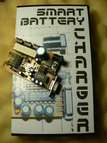
Intelligent Battery Charger
|
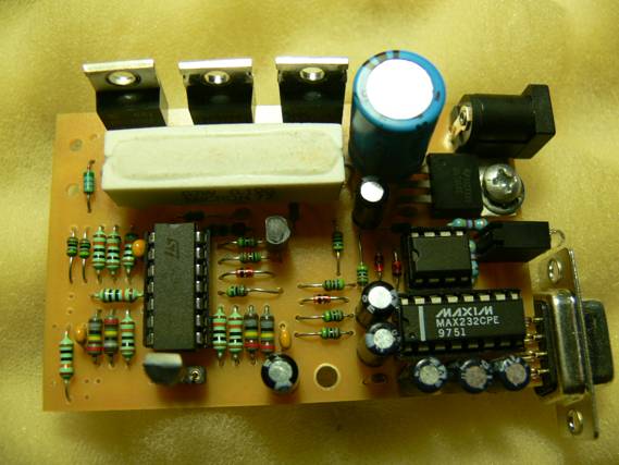
Intelligent Battery ChargerIntelligent SLA battery charger.Keith Dix ZL1BQE So who wants an intelligent battery charger? Anyone who has SLA batteries and doesn�t have a charger. The discussion below only applies to a 12 volt 7.2 Ahour SLA battery at 20C. Intelligent? Yes, one that will meet the batteries specification for charging but there doesn�t seem to be a fixed consensus on what is required so this is a best guess. I should point out that there are many chargers out there that will do a good job and there is nothing wrong with them. So far the best (low cost) one I have found uses a Unitrode �application specific device� UN3906 - this device is all the control you would need to make a good charger, even has temperature compensation which is very good,BUT, yes always a but, these devices are getting hard to get and expensive (relative term) and with this in mind I thought I could do a good charger using a small micro. The micro, yes as usual it�s a Freescale M908QT4, the same one used in a previous simple battery charger; the difference is this time we are going to monitor the voltage and current into the battery as well as the temperature. After reading several articles on charging SLA batteries there is a general agreement that a 3 stage charger is the best. Stage 1 is the trickle charge where if the initial voltage on the battery is below 10.5 volts then a low charge rate should be applied - this is set to about 100 mA. Stage 2 bulk charge applies when the voltage on the battery is greater than 10.5 volts - this stage applies the maximum charge current, in this case 2 Amps and the voltage is monitored until it reaches 14.4 volts and at this point the unit reverts to constant voltage and keeps charging until the current reduces to 3% of the AH rating of the battery (about 220 mA). It then enters stage 3 or float charge and the charger is set to constant voltage at 13.5 volts. Once at this stage the charger can be left connected to the battery indefinably. The above only applies to the 7 AH version but the parameters of the battery is stored in EEPROM so that other battery parameters can be entered via a PCs serial port The power supply used in this project is an old laptop inline supply rated at 19 Volts and 2.4 Amps and this limits the maximum charge current to 2.4 Amps but if a larger one is used (up to 5 Amps) then the maximum current can be increased to the same rating of the power supply. The maximum current for the charger is determined by the sense resistor (R1) and the gain of the OP amp that is connected across the resistor (U1c). The voltage across the resistor at maximum current should give a voltage of less than 5 volts, the maximum input to the microcontroller. The resistor and OP amp gain can be adjusted to suit any supply (within reason) and another component that needs to be taken into consideration is the pass device - this can be the IRF4905 FET or a PNP transistor could be used, you would need to consider the max amps voltage and gain of the device. The maximum voltage (number of batteries) is limited to 65 volts as this is the maximum voltage that the software can cope with and this allows up to 48 volt batteries to be charged. Again you must take into consideration the maximum rating of the pass device. Now that the limitations are out of the way how do we make it see and adjust for all the different voltages? The only hardware that needs to be changed for different voltages is the Zener diode (D2) and the voltage divider resistors (R2, R3). The criteria here is to work out the minimum and maxim voltages, for example a 48 volt battery would be just over 40 volts fully discharged and would require a boost voltage of around 58 volts, the difference between them being 10 volts but that�s what we have to measure but we will need a little above and below say 40 volts to 60 volts, so the input to the OP amp needs to be between 0 an 5 volts; if we use a 39 volt Zener then a divide by 4, we have it. The numbers are entered into the software (with a calibration adjustment) and the step size of the voltage in the above example is 20 volts divided by 255 (the number of steps in an 8 bit Analogue to Digital converter). The divider resistors don�t need to be an even value all we have to do is tell the micro mhow many volts per step for the A2D (analogue to digital converter). Temperature compensation is also provided by using a LM35DZ (U5) temperature sensor and another part of the OP amp is used to take the sensor output from 0.01 volts per degree C to .1 volt - this allows a better input range for the A2D. The maximum temperature is set at 50�C above this and the charger displays too hot and stops charging. The amount of compensation is also variable and can be entered into the software; the initial value is set at 25 mV per �C When entering the set voltages Bulk Float and Trickle these are assumed to be the voltages at 20�C and temperature compensation applied from there increasing the voltage as the temperature drops and reducing the voltage as it increases; you will note that it does not reduce the voltage at every 1� as the A2D step maybe larger/smaller than the compensation size, but it will accumulate and adjust accordingly. Keith ZL1BQE VBST $DC ; boost volts ITIM $0005 ; INTERVAL TIME in 0.2 second steps VZEN 5700T ; ZENER VOLTS IN mV VSCL 39T ; scale for volts in mV PER A2D COUNT VFLT $C8 ; FLOAT VOLTS VTKL $7B ; TRICKLE VOLTS CBST $82 ; MAX BOOST CURRENT 2.5A .02A X 125 CFLT 10T ; CURRENT LEVEL FOR REVERT TO FLOAT (x 20mA) CTKL 5T ; TRICKLE CURRENT (x 20mA) CSCL 20T ; SCALE NUMBER FOR AMPS in mA (20 x 256= 5.12A) VCAL $00 ; NOT USED CAL VOLTS CCAL $00 ; NOT USED CAL CURRENT CTMP 25t ; TEMP COMPENSATION mV PER �C ITIM $0005 ; INTERVAL TIME in 0.2 second steps VZEN 5700T ; ZENER VOLTS IN mV VSCL 39T ; scale for volts in mV PER A2D COUNT Note: ten of these battery chargers have been built at the Papakura Radio Club Projects nights and are working. If there is enough interest, a kit of parts may be considered. Keith ZL1BQE.
|
|
![]()
![]()