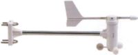
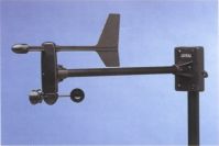
WX200 / WM918 Anenometer
Information
Wind Direction
The Wind Direction part consists of a Wind Vane mounted at the top of 20,000 ohm 360° potentiometer which has no 'end stop', which allows it to spin freely even in light winds.
One end of the 360° potentiometer is connected to a Blue wire which supplies 4.5 volts from the interconnect box, Box1, and the other end is connected to a Green wire which is grounded via Box1.
The wiper of the potentiometer taps off a proportion of the 4.5 volt supply, and returns it to the console via the Yellow wire. The connection is such that 0° gives 0 volts, and 359° gives 4.5 Volts. A 1.2 Meg-ohm resistor is also included to pull up the wiper to the 4.5 volt supply. A couple of 0.1 microfarad capacitors are wired across the potentiometer to help reduce RF interferance and wiper noise.
The signal passes through the interconnect box, and then to the console via an Orange wire , where it ultimately finds it's way to U11b, one half of a dual op-amp wired as a voltage follower (hi-impedance buffer) which in turn passes the signal to pin 3 of a Motorola™ 8-input serial Analogue to Digital converter IC, the MC145053, under control of the main microprocessor in the console.
Anenometer
The Anenometer section consists of a small reed switch connected in series to a 1,000 ohm resistor with a 0.1 microfarad capacitor are wired across the switch/resistor combination.
A Red wire and a White wire connect the unit back to the interconnect box, with the reed switch pulse emerging from the interconnect box on a Black wire. This in turn connects to a 10,000 ohm pull up resistor in the console, which also has a pair of diodes connected to clamp any excess (induced) voltages to the console's supply rails. A 1 nano-farad chip capacitor is also across the sense wire to ground, to try and reduce (sometimes unsuccessfully) any RF interferance picked up. The signal is finally presented to pin 52 on the main micro in the console.
Revolutions vs. Wind Speed
Revs/sec
Frequency |
Airspeed km/h |
Airspeed MPH |
Airspeed knots |
|
Revs/sec
Frequency |
Airspeed km/h |
Airspeed MPH |
Airspeed knots |
| 0.8 |
5.8 |
|
|
|
0.9 |
6.5 |
|
|
| 1.0 |
6.5 |
|
|
|
1.1 |
7.2 |
|
|
| 1.2 |
7.2 |
|
|
|
1.3 |
7.2 |
|
|
| 1.4 |
7.9 |
|
|
|
1.5 |
7.9 |
|
|
| 1.6 |
8.6 |
|
|
|
1.7 |
8.6 |
|
|
| 1.8 |
9.4 |
|
|
|
1.9 |
9.4 |
|
|
| 2 |
10.1 |
|
|
|
3 |
13.3 |
|
|
| 4 |
16.9 |
|
|
|
5 |
20.2 |
|
|
| 6 |
23.8 |
|
|
|
7 |
27 |
|
|
| 8 |
30.6 |
|
|
|
9 |
33.8 |
|
|
| 10 |
37.4 |
|
|
|
11 |
40.7 |
|
|
| 12 |
44.3 |
|
|
|
13 |
47.5 |
|
|
| 14 |
51.1 |
|
|
|
15 |
54.4 |
|
|
| 16 |
58.0 |
|
|
|
17 |
61.2 |
|
|
| 18 |
64.8 |
|
|
|
19 |
68.0 |
|
|
| 20 |
71.6 |
|
|
|
21 |
74.9 |
|
|
| 22 |
78.5 |
|
|
|
23 |
81.7 |
|
|
| 24 |
85.3 |
|
|
|
25 |
88.6 |
|
|
| 26 |
92.2 |
|
|
|
27 |
95.4 |
|
|
| 28 |
99.0 |
|
|
|
29 |
102.6 |
|
|
| 30 |
105.8 |
|
|
|
31 |
109.4 |
|
|
| 32 |
112.7 |
|
|
|
33 |
116.3 |
|
|
| 34 |
119.5 |
|
|
|
35 |
123.1 |
|
|
| 36 |
126.4 |
|
|
|
37 |
130.0 |
|
|
| 38 |
133.2 |
|
|
|
39 |
136.8 |
|
|
| 40 |
140.0 |
|
|
|
50 |
174.2 |
|
|
| 58 |
201.6 |
|
|
|
|
|
|
|
Disassembly
In case one needs to disassemble the unit for maintanence or repair, then the folowing proceedure should do it.
Undo the screw holding the cable at the base of the unit where it clamps to the pole to which it is mounted.
Remove the fibre washer, and carefully pull the cable out from the cable trap.
Undo the screw holding the base to the horizontal extension pole, and gently wriggle off the base from the pole.
At the anenometer end of the extension pole, there is another screw holding the two together - remove this, and separate the pole from the anenometer.
Partialy undo the small grub screww holding the wind vane by a turn or so, and pull up gently - it should detach without any troubles.
Partialy undo the screw holding the anenometer cups, and pull down to remove this.
Looking into the section where the cable disappears into the anenometer head, there is a small plastic 'flap'. Press down on this just enough to release the vane subassembly (too much will break it), and gently wriggle the vane's spindle (the thick one) out of the main body.
By pushing in the cable, and gently pulling it thru, and small PCB assembly with the anenometer sensor will slide out, still connected to the wind direction potentiometer by three wires.
At the anenometer shaft end, removing two screws will release the bearing assembly, giving access to the bearing cover and seal gasket.
Reassembly is just a matter of putting it all back together again :)
Faults
Based on experiance of others, it is possible that either the reed switch in the sensor may fail, or there may be a poor / loose solder connection on the PCB that the reed switch resides.
To check the reed, you can listen for the quiet 'plink' as the anenometer revolves - 1 'plink' per turn - if you don't hear it, it means that either it has failed, or your surrounds are too noisy to allow you to hear it. As for anything else, you are going to have to open it up to see.
There is always the chance that a wire has been nicked, either cutting the wire or allowing moisture to seep in and corroding the wire. This means that the wire will need to be changed.
If you want to check the loop up to the anenometer is ok, pull it apart, and short out the reed switch with a fine screwdriver or something metallic - be careful that you don't place too much force against the wire leads from the reed switch to the PCB, as the reed is real easy to crack, and then you _will_ need a new one.
This will make a small windspeed reading on the console, for as long as you short / unshort out the reed.
If you have access to a voltmeter / multimeter and know how to drive it, check between the red and white wires - the two outer wires - should be about 5.5 volts there until the reed closes - then it should drop to around 0.5 volts or so - it'll be a quick pulse, so you may not see the 0.5 volts unless rotate the cups very slowly, and find the point at which the reed closes...

Updated 23:57 4/8/2001.
