WX200 / WM918 Interconnect Box
Wiring inside the Interconnect Box - Box 1
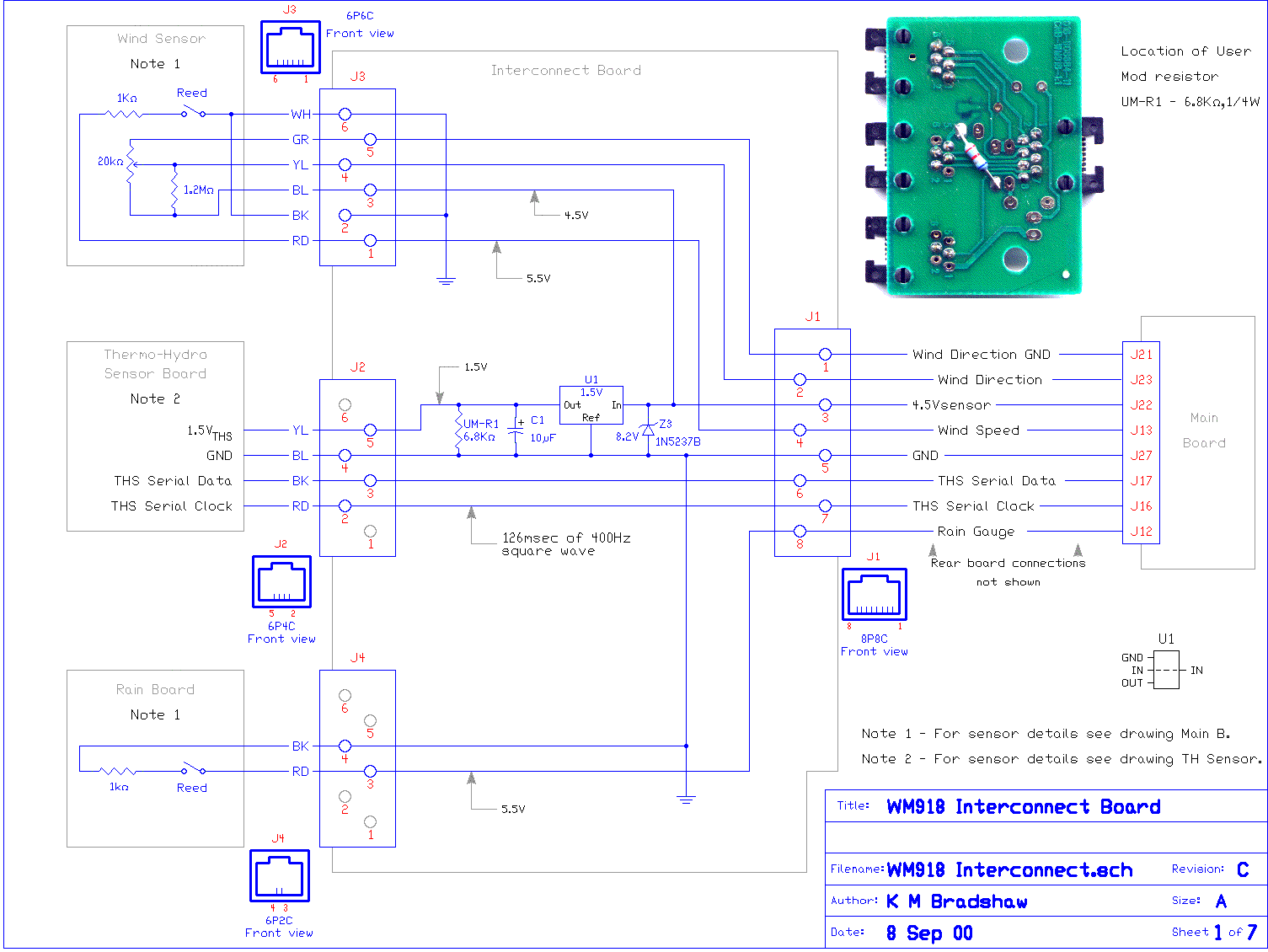
 The Interconnect Box's purpose is to collect the signals from the Temperature / Humidity Sensor, the Wind Speed & Direction Sensor, and Rainfall Sensor and pass them on to the console of the WX200 / WM918 Weather Station.
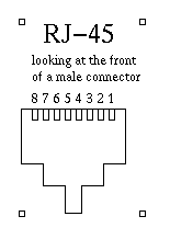
It has 4 modular sockets, for 4 modular plugs. Looking at the plug, with the locking tab below and the gold pins horizontal and visible, with the cable away from you, and the plug pointed towards you, pin one is on the right and pin 6 or 8 is on the left. Some plugs only have some middle pins present i.e A 6-way plug with 4 gold pins present is termed a 6P4C and a 6-way plug with 2 gold pins present is termed a 6P2C etc.
This cable is an 8-way 'straight-through' type of lead, i.e. pin 1 at one end goes to pin 1 at the other, pin 2 to pin 2, etc. A computer network patch cable which is used to join a computer to the socket on the wall, or to a hub or router is suitable to use as a replacement.
The type which is NOT suitable, is a 'crossover' cable, which is used to join two computers directly to each other.
How to tell the two type apart? Compare the colours of the wires in the plugs at both ends, placing the two plugs side-by-side - if the colours match, it's the right cable!
If one already has a handy Cat-5 cable near where the weather station will be placed, then it can be easily 'patched in' to the cable, with a suitable RJ-45 socket, such as a Krone or other brand socket near where the other end is desired.
Jack # 1 ( 8P8C or RJ-45 ) goes to the WX200 / WM918 Console.
- Pin 1 (Blue Wire) connects to pin 5, jack 3, and is the Wind Direction Sensor Ground Return - an analogue signal connected to ground back at the WX-200 / WM-918
- Pin 2 (Orange Wire) connects to pin 4, jack 3, and is the Wind Direction Sensor Signal - an analogue voltage derived from a potentiometer which varies with the wind direction - 0° 0 volts, 359° 4.5 Volts (max).
- Pin 3 (Black Wire ) connects to pin 1, jack 3, and is the Wind Speed Sensor Signal - a digital signal from a Reed Switch sitting under the Anenometer head - sends out 1 pulse per revolution.
Also connected to this line is a 8.2 Volt 1/2 watt Zener Diode Z3 clamping any excess voltage to ground.
- Pin 4 (Red Wire) connects to pin 3, jack 3, and is the Wind Speed Sensor's 4.5 Volt supply rail - a reference voltage connected to the top end of the Anenometer's direction potentiometer.
Pin 4 *also* connects to the In pin of a 1.5 volt, 3-terminal Surface Mount Voltage Regulator in the interconnect box.
- Pin 5 (Green Wire) connects to common ground, and pin 4 jack 2, pins 2 and 6 jack 3, and pin 4, jack 4.
- Pin 6 (Yellow Wire) connects to pin 3, jack 2, and is the Serial Clock signal (1.5 volts peak) from the Temp / Humidity Sensor.
- Pin 7 (Brown Wire) connects to pin 2, jack 2, and is the Serial Data signal (1.5 volts peak) from the Temp / Humidity Sensor.
- Pin 6 (Grey Wire) connects to pin 3, jack 4, and is a digital signal from the Rain Gauge. One pulse as the little 'bucket' flops across to the other side in the Rain Sensor.
 Jack # 2 ( 6P4C ) goes to the Temp / Humidity Sensor,
- Pin 1 is not used, or is grounded.
- Pin 2 (Red Wire) connects to pin 7, jack 1, and is the Serial Data signal from the Temp / Humidity Sensor to the WX-200 / WM-918.
- Pin 3 (Black Wire ) connects to pin 6, jack 1, and is the Serial Clock signal from the Temp / Humidity Sensor to the WX-200 / WM-918.
- Pin 4 (Blue Wire) connects to common ground.
- Pin 5 (Yellow Wire) connects to the Out pin of a 1.5 volt, a 3-terminal Surface Mount Voltage Regulator in the interconnect box and the positive leg of C1, a 47uF electrolytic capacitor to ground. The modification adds a 6800 ohm 1/4 watt resistor from the positive leg of C1 to ground, to ensure C1 discharges completely and resets the Temp / Humidity Sensor. See Picture
- Pin 6 is not used, or is grounded.
Jack # 3 ( 6P6C ) to the Wind Speed / Direction sensor.
- Pin 1 (Red Wire) connects to pin 3, jack 1, and is the Wind Speed Sensor Signal - a digital signal from a Reed Switch sitting under the Anenometer head - sends out 1 pulse per revolution.
Also connected to this line is a 8.2 Volt 1/2 watt Zener Diode Z3 clamping any excess voltage to ground.
- Pin 2 (Black Wire ) connects to common ground.
- Pin 3 (Blue Wire) connects to pin 4, jack 1, and is the Wind Speed Sensor's 4.5 Volt supply rail - a reference voltage connected to the top end of the Anenometer's direction potentiometer.
Pin 3 *also* connects to the In pin of a 1.5 volt, 3-terminal Surface Mount Voltage Regulator in the interconnect box.
- Pin 4 (Yellow Wire) connects to pin 2, jack 1, and is the Wind Direction Sensor Signal - an analogue voltage derived from a potentiometer which varies with the wind direction - 0° 0 volts, 359° 4.5 Volts (max).
- Pin 5 (Green Wire) connects to pin 1, jack 1, and is the Wind Direction Sensor Ground Return - an analogue signal connected to ground back at the WX-200 / WM-918
- Pin 6 (White Wire) connects to common ground.
Jack # 4 ( 6P2C ) to the rainfall sensor.
- Pin 1 is not used, or is grounded.
- Pin 2 is not used, or is grounded.
- Pin 3 (Red Wire) connects to pin 8, jack 1, and is a digital signal from the Rain Gauge. One pulse as the little 'bucket' flops across to the other side in the Rain Sensor.
- Pin 4 (Black Wire ) connects to common ground.
- Pin 5 is not used, or is grounded.
- Pin 6 is not used, or is grounded.

Updated 02:39 17/12/2000.
