
Antennas and Other Bits....
During the course of my ham radio hobby I have made many
sorts of antennas from HF through to Microwave.
The following bits will
hopefully be of use to others.
Making Loop Yagis.
I needed to make a loop yagi for the 1296 Transverter and decided on a loop
yagi for robustness and reliability. I picked up a QST article that has the
details on how to build one.
Refer to QST Article "Loop Yagis for 23cm" by
Chip Angle N6CA, it is in the ARRL Handbook. I decided to make mine a bit bigger
by adding more directors than what was in the article for more gain.
What I found was there was difficulty in getting the hardline and the N
Bulkhead connector here in ZL so I set about making one out of old bits of in
line N connectors from the junk box.
I had a few old female bodies without
the inner bits and the cable locking parts. Since I needed a small hole for the
hardline, I managed to get a friend to lathe turn a threaded plug to fit the
body.
The hardline was the other problem but Harry ZL1BK has made loop
yagis before and used rigid RG58 coax inner and a piece of 5/32" (3.93mm) OD
copper tubing from model shops. This will take the inner with a comfortable
fit with no problems.
Before fitting the inner, it is good to make the
copper more malliable by heating where you intend to bend it so it will bend
easily without crushing the inner dielectric.
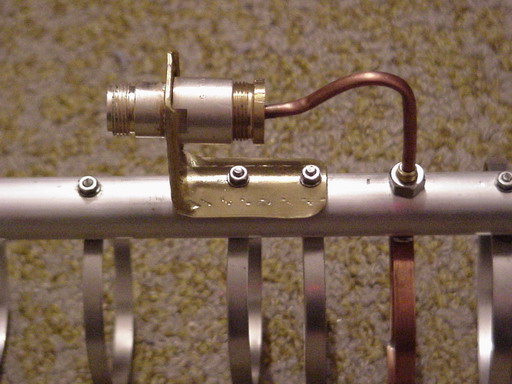
Assemble the bracket that will hold the connector. I used thick brass sheet from a scrap merchant and put small folds down each side to give it strength. Drill a hole to fit the N connector body as you will need to sweat solder the body to the brass support. Please make sure that you have none of the N connector parts in the body when heating it up, they will melt!! I found it easy to sweat solder the connector to the support, just make sure all parts are shiny and clean.
 |
 | |
|
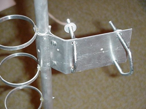
The Feedline and Bracket |
Making a clamp something |
 |
 | |
|
Fabricated N connector inner with |
Another view - note how I have countersunk the end to avoid any shorts with the inner pin. This ring mates against the bottom of the socket well near the centre pin. Don't want long earth paths at uWave! |
A DIY Dual Band Mobile Whip.
I
have built several of these antennas and they work just fine. They have
broad bandwidth and can be built from the junk box mainly.
You need the following Items...
A small length to plastic
rod of 12.5mm diameter.
A surplus mobile whip such as seen on Police cars
of about 875mm long.
A 4.7pf cap that has the highest voltage rating
possible.
The whip mounting base that screws onto the main
base.
Please see the diagram and the picture of the
prototype. The diagram shows the units without covering but you will need to
cover with selaf amalgamating tape etc..

