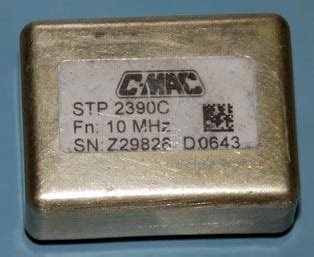
I used an elderly C-MAC CFPO-2 10 MHz OCXO. While any 10 MHz OCXO with positive-going EFC would work,
a really high performance device is well justified by the performance that can be achieved. Use a
12 V device, and mount it as far away as possible from the TIC circuit, to minimise thermal effects
which can ruin the Allan Deviation (stability) at 100 sec Tau and greater.
Many suitable devices, such as the one illustrated, are available on the Internet, but it is unfortunately easy to
end up with a dud. Going prices are around $30 to $50. Check the specifications before you buy,
and once the device arrives, test it thoroughly before committing to it. You need not select a double-oven
device, as many newer single-oven devices can be as good or better, and are smaller and use less power.
Check the specs carefully.
The OCXO power and ground leads should be separately supplied from the incoming source, to prevent
high oven current from affecting the stability of the rest of the design. Ground the OCXO to the
board, but ground the supply and the circuit board at the OCXO. Input to the 5 V regulator
should from the supply, not the OCXO. Expect a 12 V OCXO to draw at least 500 mA cold, up to 150 mA
warm. You could use a 5 V OCXO, but the 5 V regulator would need to have a rather bigger heatsink.
The OCXO drives a 74HC4060, which is mainly used as a buffer for the sinewave output of the OCXO,
but it is also a divider. As well as providing a buffered 10 MHz output for the further dividers,
it also furnishes a range of binary divisions from 10 MHz which you might find useful: for example
1.25 MHz, 625 kHz. But you could just as easily use one of the 74HC04 gates (described later) as
the buffer, provided it doesn't lead to excessive hook-up wire or track lengths.
As the decimal divider I used a 74HC160 synchronous counter (since I had one). This provides the
1 MHz required by the TIC, and 5 MHz required by the micro timer. DO NOT use a ripple
counter such as the 74HC90.

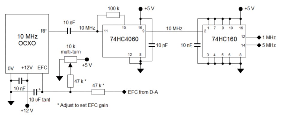
The OCXO and Divider circuit.
(Click on the picture for a full-size diagram you can print).
If the OCXO has sine-wave output, use a 10 nF series capacitor as shown. If it has 5V TTL or CMOS
output, you could omit the capacitor, or completely omit the 74HC4060 chip, driving the 74HC160 directly.
The two resistors adjacent to the EFC pin of the OCXO may need adjustment once you have the unit
working. These set the system gain relative to the gain of the frequency trim pot. The gain from
the micro D-A should be as low as possible, in order to maximise the overall stability.
A compromise is required, as setting the gain too low will require more frequent attention to the
trim pot as the OCXO ages. Aim for several year's running between tweaks. The better the OCXO,
the easier it will be to achieve a suitable gain compromise.
The 5 V supply to the trim pot as shown needs to be very clean - if the OCXO has a reference
output pin (many good ones do), use that for preference. The trim pot should be a multi-turn type,
and ideally should be on the back panel or accessible through a hole in the panel.
It would be a good idea to build and fire up this part of the design before continuing. Run it
for some weeks while you build the rest of the circuitry. This allows the OCXO to 'age in', and
allows you to gauge how stable it is (assuming you have an even better reference source to compare
it with). As a rule of thumb, it takes about a day of continuous operation for each month of
previous inactivity for a top quality OCXO to settle. Once it has settled, the drift should ideally be less than 1 ppb per day. Drift of this order is difficult to measure by conventional means.
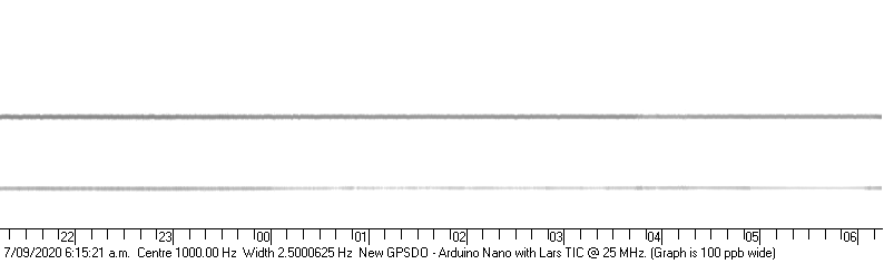
Illustration of GPSDO stability using SBSpectrum.
This chart, recorded using SBSpectrum at 25 MHz, shows the 5th harmonic of the 5 MHz output of the
GPSDO marching across the centre of the chart with no noise or instability. The signal was received
using a JRC NRD-93 receiver on USB, set to 24,999.000 kHz, which of course results in a 1 kHz tone
from the GPSDO signal. The receiver uses an excellent HP E1938A OCXO as its reference.
The other weaker signal below is one of my NEXC Exciter/Generators running
at 25 MHz, with a slight frequency error due to synthesizer limitations. It has a 26 MHz OCXO reference,
not GPS locked.
This measurement technique (with excellent receiver and SBSpectrum) only has a resolution of 0.4 ppb, not enough
for analysis of a good GPSDO. Once the GPSDO is complete, you will be able run TimeLab and observe the
performance well below the 1 ppb level.
Introduction
Buffers
TIC Circuit
Micro & Misc.
Copyright � M. Greenman 2020.
All rights reserved. Contact the author before using any of this material.