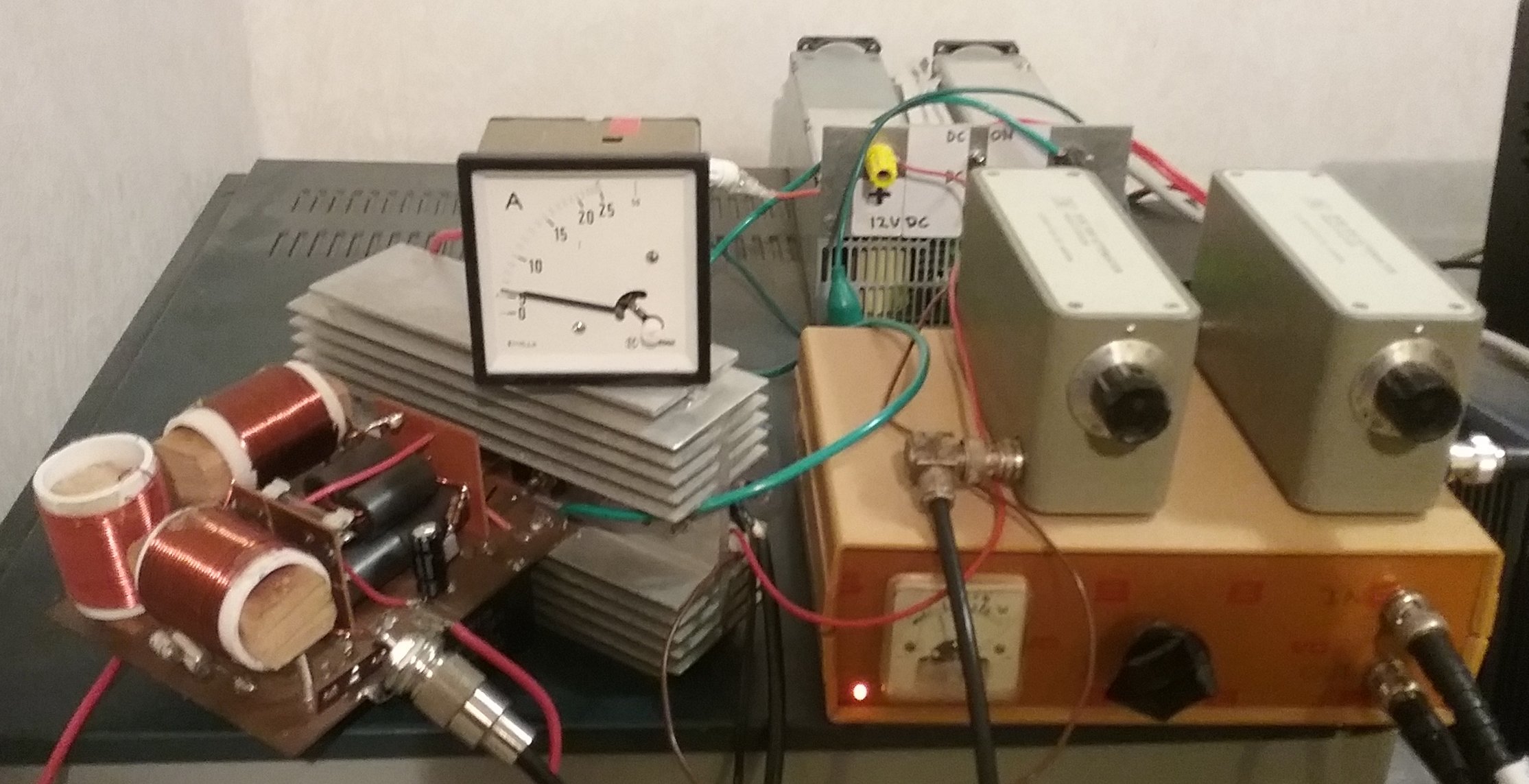
The final setup: power amp (left), transverter (right) and power supply (behind)
(Click on picture for full size view)
While 630 m is predominantly a home-brewer’s band (since commercial equipment for this band is rare and expensive), that doesn’t make it impossible to put together an effective station, and in this series of articles I will describe a transverter and a power amplifier, that can be made with locally sourced or junk-box parts. These are two pieces of equipment I use myself – at night I can be received in Hawaii regularly, and occasionally make it to Western Australia as well. Ground wave range (daytime operation) is easily 350 km.
I will give construction details for these two pieces of gear – all you will need to transmit on 630 metres, apart from an HF SSB transceiver, power supplies and some antennae. The transverter should cost under $30 to make, and the power amplifier under $100, even less if the junk box is generous. The first part is the transverter – so you can soon have your own signal on the band!
This first picture shows the whole setup, transverter and power amp, in operation on low power. The meter indicates drain current. Ignore the two attenuator boxes on top - they aren't needed. The power supply is a switch-mode type, 12 V 30 A and 5 V 30 A, from an old computer server.
Operating 630 m requires quite different strategies from those used on higher bands. Because antenna efficiencies are generally very low, signals are weaker than you would expect on higher bands, making weak signal reception capability the highest priority. It also doesn’t hurt to run a lot of transmitter power.
In New Zealand the legal limit on this band is 25 W EIRP, which, given a typical urban MF antenna efficiency of 1%, means that you could run 2.5 kW output, if you could afford to! I run 100 W (EIRP 1 W), and have a suitably big signal, even with a tiny antenna, only 0.01 wavelengths high.
Choosing a Transceiver
I use an old synthesised marine radio, the Kenwood TKM-707 (1989), which covers all HF frequencies, but a previous owner removed the power amplifier, so I’m left with just a few mW output – perfect for this project.
The next choice is to decide what frequency to use as the mix-down oscillator. I used a 10.0 MHz TCXO, as I wanted uncompromised stability for WSPR operation. You can use a conventional crystal oscillator, but I don’t advise it. For weak signal operating on 630m you need better than 1 Hz stability, so the transceiver and the oscillator must be even better than that. (At 10 MHz, 1 Hz is 0.1 ppm).
The frequency you choose on HF may have a lot to do with what oscillator you can find. With a 10 MHz TCXO (plenty available mail-order for $15 or so), you can operate the transceiver near the 30m band, at 10.474 MHz. The transceiver operating frequency should be 474 kHz higher than the mix-down oscillator frequency, in order to not invert the signal and tuning sense.
If the chosen transceiver is crystal-controlled, you might prefer to use a synthesiser kit of some sort
to act as the transverter mix-down oscillator. There are plenty of suitable kits available.
The transverter design is also easily adaptable to the 2200 m (136 kHz) or 160 m (1.8 MHz) bands,
although the output coils and filter component values would need to be recalculated.
Transverter Design
The description starts with the TCXO in the top left-hand corner, U1. I used a voltage trimmed device, hence VR1, but a mechanically trimmed TCXO would suffice. With it trimmed to exactly 10.000 MHz, you will have no worries about your operating frequency.
The local oscillator needs to be a 5V rated Temperature Compensated Xtal Oscillator (TCXO). Be cautious, as many packaged oscillators don’t have the necessary 0.5ppm or better stability performance. They might look good, but most are simple uncompensated oscillators. The device I used had CMOS output, but a sine wave one would also be OK. An OCXO (Oven Controlled Xtal Oscillator) would be ideal if you have one, but they use more power and are more expensive to buy.
TR1 is a simple Class A buffer, required to generate sufficient level to drive the passive mixer. Between +6 and +10 dBm is required. If you have too much, increase the value of TR1’s emitter resistor. If you don’t have a way to measure the drive, just go with the value suggested.
The input from the SSB transceiver has a simple Drive control pot VR2, mounted on the front panel for convenience. MF transmitters can be fussy regarding drive level, so a convenient adjustment is most useful. A good sized carbon or wire-wound pot from your junk box will work fine at 10 MHz. I can adjust the transverter output from under 10 mW to over 600 mW with this control.
The three resistors following the pot serve to add further attenuation and ensure a good termination to the mixer input.
U3 is a passive diode mixer. It has two tiny transformers and four diodes inside. If you don’t have one to hand, and don’t want to buy one, you can easily make your own with two small toroids and four good RF diodes. Copy the ones in the
BITX40 transceiver.
The ‘IF’ output of the mixer is used as the output port, as it is internally DC coupled and so has very good performance at 474 kHz and even lower. Most of the unwanted higher mixing products are shunted to ground by the following 100nF capacitor. TR2 is a simple Class A wide-band amplifier. The main departure from the G3XBM design is the use of a bipolar transistor for TR3. I only needed 100 mW or so, so chose to use a 2N3053 instead of the IRF510 FET used in the original design. If you want to operate barefoot and would like to have 7W output, build the G3XBM output stage, but make sure to include the extra 5-pole low pass filter. You
will also need a 20 dB attenuator when you later drive an amplifier. I use an external 150W amplifier, which has its own low pass filters.
TR3 operates in Class AB. Not much current is drawn until drive arrives, at which time the transistor current climbs up to almost 100 mA, depending on the drive level at 10 MHz. TR3 will need a small heatsink.
The transverter is completely stable, runs cool, and the output is pleasingly clean. Power remains on all the time, as it generates no noise on receive when there is no 10 MHz drive. The driving transceiver has PTT control in the conventional manner. If you don't have a suitable SSB transceiver, for CW operation it is
easy enough to drive the transverter from a suitably stable signal generator at 10.474 MHz, but you’d need to devise a way to key it. If you don’t wish to use a transceiver, there are DDS synthesisers and kits that can be controlled to generate CW and QRSS, even WSPR.
As you can see from the picture above, I fitted an optional output level meter, which was nothing more
than a 25V Schottky diode connected to the output socket, then a 100 nF bypass capacitor and a 10V FSD meter. A 100 uA movement with a series 100k resistor would do. Fit a 1k resistor across the transverter output socket to act as a return path for
the diode. The meter will indicate about 1 W full scale. I also fitted a power indicator LED, visibile
bottom left, and which is also shown on the schematic.
Construction
The TCXO U1 and double-balanced mixer U3 are mounted ‘dead bug’ style directly to the baseboard. The baseboard is about 120 x 80 mm, and fits nicely inside a recycled DSE case, with a new PCB laminate
front panel accommodating the meter, power LED, drive control and BNC input and output connectors.
The 12V power lead goes in the back.
The layout more-or-less follows that of the schematic, with the TCXO U1 top left, the mixer U3 below it, and the output stage and low pass filter to the right. The strange curved bracket about in the middle
is the heat radiator on the output transistor, which is a TO5 device.
Most of the components are non-critical, and don’t have part numbers. The 10 nF and 100 nF capacitors are monolithic ceramic. Others are disc ceramic. The important parts are:
Trim the TCXO exactly to frequency against a traceable reference (don’t use WWV!). Use a frequency counter connected at TR1 emitter. You may need to revisit the TCXO after a week or two to give it another tweak.
Apply a 50 Ohm dummy load and power meter to the output, connect up the transceiver to the input, select AM mode and dial up 10.474 MHz (or whatever frequency is required for your chosen local oscillator). Set the Drive control to minimum. Press the microphone button on the transceiver, and then carefully wind up the Drive. I had no trouble at all achieving sufficient drive, and when I used the computer to drive the transceiver on SSB with WSPR or QRSS modes, there was more than enough drive to achieve 700 mW output. TR3 will get a bit warm if you do that for too long!
If you wish to have more output, use an IRF510 FET, as it is more efficient and gives rather more output power. Follow the G3XBM design.
The transverter is reasonably linear, but since virtually all MF power amplifiers are non-linear,
there’s little point in being fussy. I have tried the transverter barefoot on AM and SSB, and it sounds good.
Given an adequate 630m transmitting antenna (see Firing Up), this transverter operated barefoot should be easily heard across town during the day, and several hundred km at night. If you don’t have a suitable antenna yet, visit one of your local 630m operators to try out your new toy.
The Transverter
The transverter converts signals from a conventional HF SSB transceiver down to 474 kHz. This approach allows you to use CW, QRSS, WSPR, WSQCall and even SSB. It is transmit-only, so you need to make separate arrangements for reception. Given that an active antenna is usually the best solution for reception, a separate receiver is an acceptable option. With most transceivers it can also be awkward to operate split frequency as would be required, and you’d not want to accidentally transmit into an active antenna!
The transverter design is fairly adaptable, so you could start on any band, such as 80 m, 40 m or 30 m. Before you make such decisions though, you need to consider the transceiver you will use. Some commercial QRP transceivers such as the Elecraft range, the Yaesu FT817 and the BITX40 can easily be operated at very low power, which you will need to drive the transverter. Any other transceiver will either have to be adapted to suit, or used with a 100 W 20 dB or 30 dB attenuator. The input to the transverter needs to be about 10 mW. One possible SSB exciter would be a recycled marine or land-mobile radio, as these are easily adapted by simply disabling the power amplifier, but if the transceiver is crystal controlled, it limits your operating frequency options considerably.
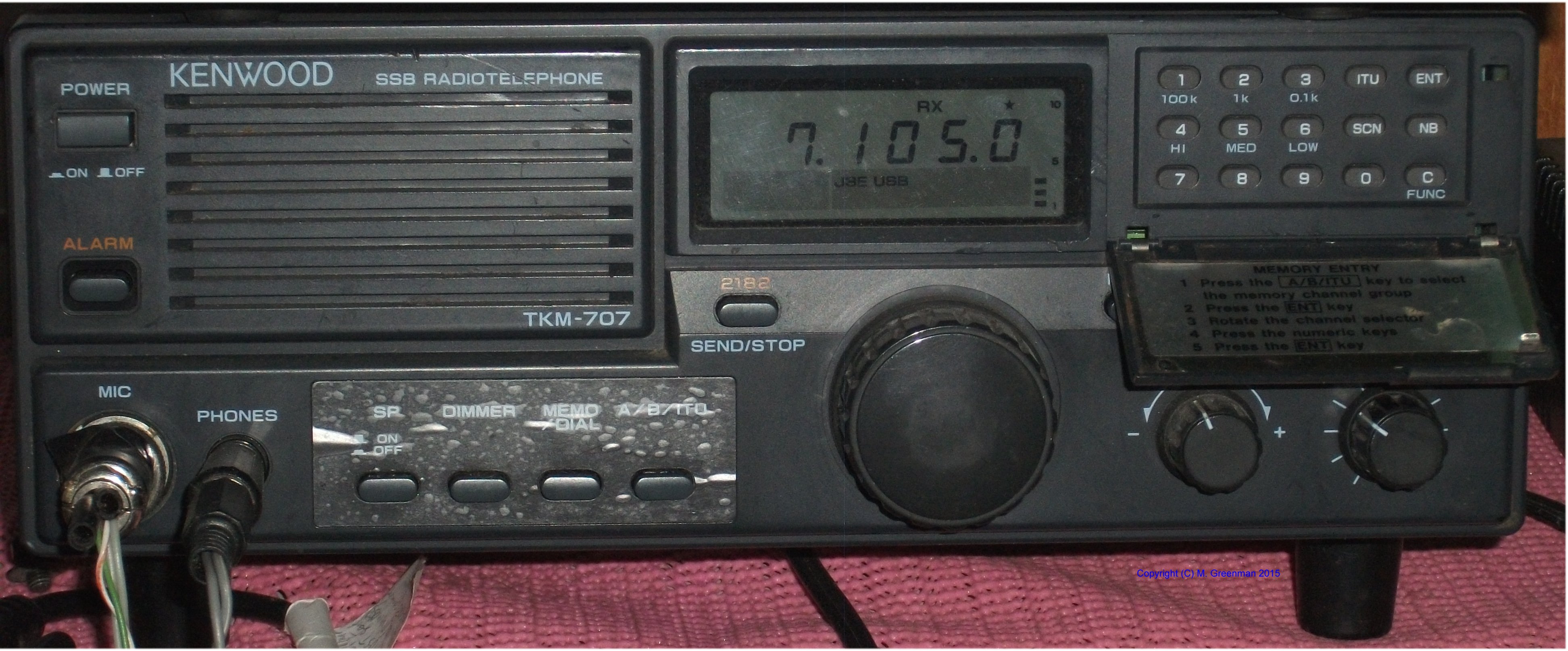
The Kenwood TKM-707 marine transceiver
(Click on picture for full size view)
The transverter is simplicity itself. It is based on a popular design by
G3XBM.
There is a local oscillator (say 10 MHz), a buffer, a double balanced mixer, and two amplifier stages. Just three cheap transistors are used. Check out the schematic below.
The Transverter schematic
(Click on picture for full size view)
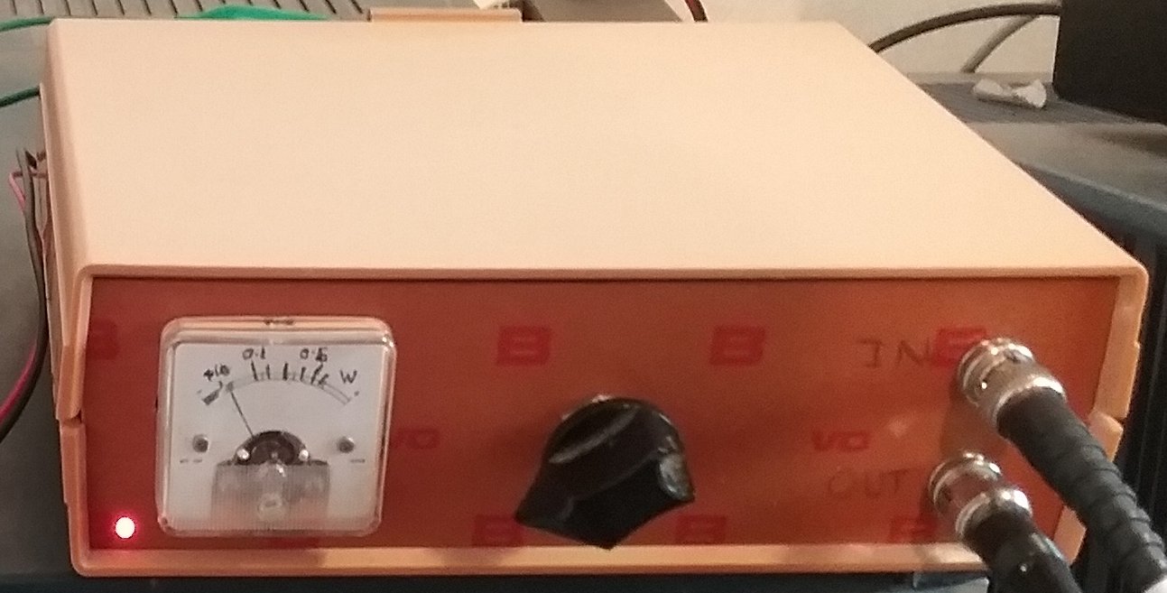
Front view of the Transverter
(Click on picture for full size view)
As you can see in the next picture, I constructed each stage on a small rectangle of copper-clad board,
so I could test them as I went along. I milled appropriate pads using a drill press.
The small rectangles are mounted on a larger copper-clad baseboard, and are soldered down to it. Double-sided tape is useful. The input and output networks have their own little rectangles.
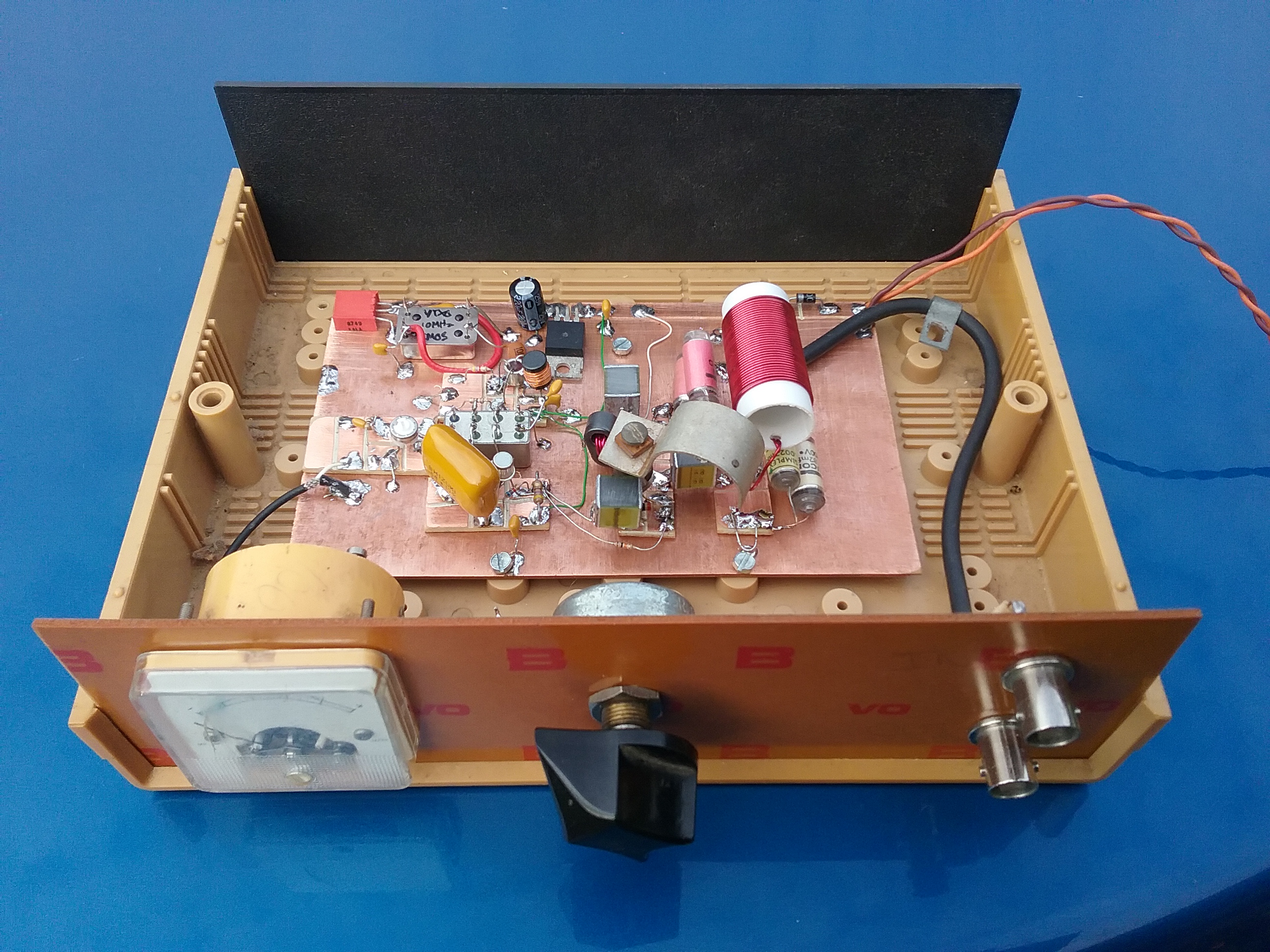
Inside view of the Transverter
(Click on picture for full size view)
After a careful check of the wiring, the first thing to do is apply power and check for smoke! Check for the correct supply voltage on U1 and on TR3 collector. Check that U1 runs cold.
Copyright © M. Greenman 1997-2018.
All rights reserved. Contact the author before using any of this material.