Saga of an LF Transmitter
for
Amateur 136, 180 and 500kHz Bands
Recycling a Southern Avionics SC1000 DGPS USCG Dual Transmitter
Specifications
Transmitter Overview
Detailed Description
Commissioning the TX
Build your Own
ZL1BPU LF Station
History
In mid October 2005 I was offered an ex-Navy LF transmitter at a price that was hard to refuse. What was on offer was damaged,
but relatively new, dual 1kW solid state high quality US made transmitter, designed for transmitting DGPS corrections in the 283.5 to 325kHz band.
This isn't the same sort of beast as a marine or aviation navigational beacon transmitter (NDB), but a purpose built unit for transmitting MSK data.
Obviously there are certain similarities to an NDB, and I expect that some of the same modules are used in other transmitters made by the manufacturer of my unit,
Southern Avionics.
There web site gives plenty of detail of this model (yes, it's a current model!), including an illustrated Specifications Document and a
coloured brochure. The Antenna Tuner is also described.
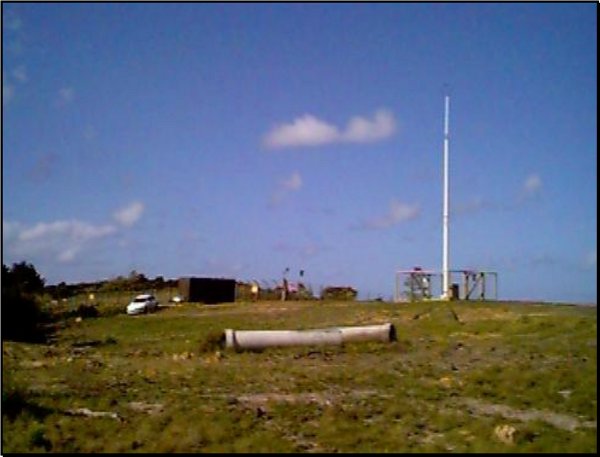
I understand that the unit was imported for the America's Cup Regattas, and was commissioned in June 1999. The serial number is 9576A00001. The transmitter was installed in a special caravan on a hilltop site
(photo courtesy of Trimble NZ) on the Whangaparaoa Peninsula, and remained there until withdrawn from service. It operated on 294kHz. At some time in its short but exciting life, it received a fairly decent lightning strike, which probably precipitated its retirement from active service in mid 2005. There are no plans to replace it, and thus there is no LF DGPS service in New Zealand. My transmitter is apparently the only one ever imported.
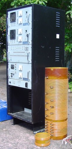
The picture to the right is the SC1000 DGPS USCG as received. At the top of this 2m high rack unit are two identical units, the two 1000W
transmitter drawers. Below that the controller unit, then the charger, an inverter, and finally an open space where, behind a blank panel, now lost, resided the three huge power transformers and the main AC contactors. The cylindrical object on the right is the antenna series loading coil, with its variometer coil in front. The antenna coil is adjustable via taps from 25 to 650µH, and the shorted-turn variometer gave 5% manual or automatic adjustment.
Mounted in a large metal box (which I don't have) were twelve 50AH sealed lead-acid batteries, used to power the transmitter
(at almost full output power),
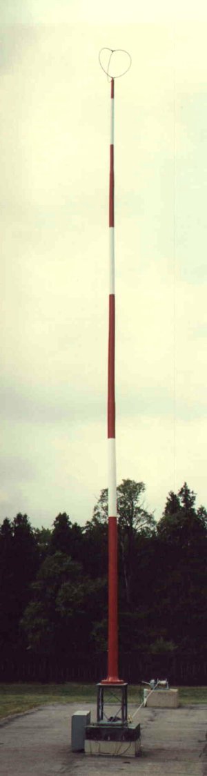
during periods of AC power failure. The automatic Antenna Tuner was mounted in a special waterproof enclosure (destroyed by lightning) close to the antenna (see picture). The antenna was a 15m tall fibreglass loaded vertical, the Valcon V-147-CL2 FT.
The antenna current was 3A at about 300W output. A substantial ground system was installed under the antenna. This type of transmitter is also often used with a Marconi top-loaded two-wire T antenna 100m long, supported from two 30m masts.
Collection Day
After weeks of impatience, the day for collection finally came - Tuesday 22 November 2005. I took my trusty (that should read 'rusty') old trailer over to the Devonport Naval Base, paid my money, and loaded up. The kind sailor who helped me load, nonchalantly placed all the batteries (15kg each!) in the trailer, and I quickly found that all the air in the tyres had gone to the top! I carefully transferred the batteries one at a time to the floor of the car, front and back, and put the transformers in the boot. The first stop was the gas station to take on more air in the trailer tyres. The next picture shows the whole setup as it arrived home - a 60km trip with no mishaps. And it didn't even rain on the way home!
 Note how low the back of the car is! There were six batteries on the floor behind the front seats, and another four on the floor in the front. The rest were on the trailer. The rack unit rode on its side in the trailer (on a blanket, packed with rubber foam), and the rest of the bits were in the car boot. The heavy transformers were also in the boot.
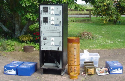 The next picture shows exactly what I got for my money. Here it all is, all lined up after I'd unloaded the car and trailer. On the left, eight of the 12V 50AH sealed long-life batteries. Next, the main rack unit, about 2m high. The brown cylindrical object is the antenna tuning coil, made of about 90 turns of bifilar 3mm diameter Litz wire. The coil is nearly 1m long, and is 270mm diameter. In front is a smaller coil, which fits inside the big coil and acts as a variometer. It is in fact just eight turns, shorted.
To the right are the three huge transformers (115/230V primary, one for each transmitter and a bigger one for the charger), and behind a plastic box full of spares (although I later discovered that many of the 'spares' were actually pulled out of the transmitter!). Then to the right the antenna matching panel, with toroidal matching coil, switch, and antenna current meter, and finally the rest of the batteries.
Initial Impressions
Of course, the first thing I did was took it all apart to see what I had! One transmitter tray seemed fairly complete, but the other was completely without boards, although I did discover them in the box of goodies. Each transmitter apparently consists of two amplifier sections followed by a low pass filter and a combiner. Each amplifier section consists of two boards plugged into a mother board.
Hundreds of screws that needed to be unscrewed to dismantle the unit for transport have been lost. Since these are US thread, finding
replacements will be quite a picnic! The lower front blank panel and the ventilated rear cover have also been lost. There are no battery
straps or leads, and the Antenna Tuner cabinet and feedthrough insulator are missing. I suspect the good loading coil I have was a spare, as
it is completely undamaged and looks new.
One board in each transmitter section has bridge-type power amplifier, four IRF250 devices (Class D) and a modulator/power supply, two IRF244s and some big ferrites (PWM type). To amplify MSK one should not need a modulator, so what is it for? The transmitter envelope is not modulated at the data rate, and the modulator only serves as an efficient supply adjusted for power level control. Very likely the same module is used in NDB transmitters for AM applications.
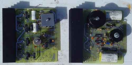
 The upper picture shows the top view of the modules. A PA module is on the left, and a modulator module on the right. The boards are about 150mm square.
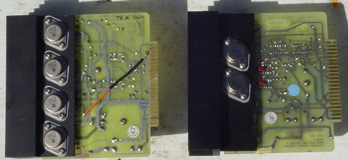
The lower picture shows the bottom view of the modules, so you can see the power devices. Once again, the PA module is on the left, and a modulator module on the right. Considering that each is a 500W module, the heatsinks are quite small. The heatsinks are blown by a 24V fan mounted in the front of the tray. It really shows how efficient a switching amplifier can be!
The upper picture shows the top view of the modules. A PA module is on the left, and a modulator module on the right. The boards are about 150mm square.
The lower picture shows the bottom view of the modules, so you can see the power devices. Once again, the PA module is on the left, and a modulator module on the right. Considering that each is a 500W module, the heatsinks are quite small. The heatsinks are blown by a 24V fan mounted in the front of the tray. It really shows how efficient a switching amplifier can be!
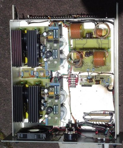
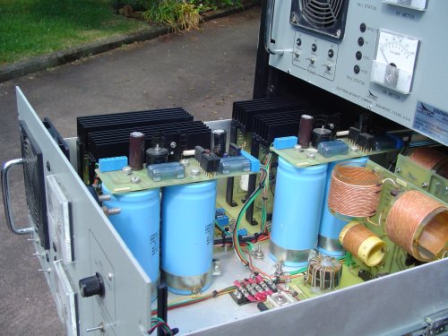 The next picture gives a nice side view of the transmitter tray. The two amplifier/modulator pairs are on the far side, where each pair plugs into an interconnecting mother board. The power supply boards and fat
blue HV supply filter capacitors run down the centre, while on the near side at the back are the low pass filter boards, one for each transmitter section, which plug into a mother board carrying the combiner toroidal transformers, one of which can be clearly seen. All the coils are wound with Litz wire. The whole design is reasonably broadband except for the low pass filter boards, and the unit should operate anywhere from 136 to 500kHz by rewinding the filters.
The next picture gives a nice side view of the transmitter tray. The two amplifier/modulator pairs are on the far side, where each pair plugs into an interconnecting mother board. The power supply boards and fat
blue HV supply filter capacitors run down the centre, while on the near side at the back are the low pass filter boards, one for each transmitter section, which plug into a mother board carrying the combiner toroidal transformers, one of which can be clearly seen. All the coils are wound with Litz wire. The whole design is reasonably broadband except for the low pass filter boards, and the unit should operate anywhere from 136 to 500kHz by rewinding the filters.
Two small boards fit in slots at the front (not fitted here). One is a controller board, the other the transmitter driver board. Take another look at the transmitter tray from the top and compare it with the drawing alongside - these are shown below. Make sure you make your browser full-screen, or they won't appear side by side. If you have a measly low resolution display, tough!

Left/top - drawing of transmitter tray (Click on drawing for a bigger view). Right/bottom - plan view of transmitter tray
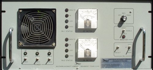
You might be interested to see an equivalent pair of pictures of the front of the transmitter. The black thing at the left is the cooling fan, with three switches
and LEDs below (AC, DC and RF ENABLE/OFF). To the right of this down the centre is a row of status LEDs, one for just about everything, and two meters. The upper one is the RF meter, labelled 0 - 200% Power (100% means 1kW), Forward and Reverse. The lower meter is the PA meter, and has two scales 0 - 150V and 0 - 8A. To the right are a few more switches. The top one is the SWR switch (OFF/FWD/RFL).
As far as I can determine, the two transmitters were identical apart for serial number (A and B suffix). There's not much on the back - a BNC input connector (drive) and an N type output connector, plus a series of connector strips for the main harness. These can be seen in the previous top view drawing and photo.

Left/top - drawing of transmitter tray (Click on drawing for a bigger view). Right/bottom - top view of transmitter tray
The transmitter design looks very interesting. Each section consists of a power amplifier and supply modulator (to give power level control, and AM in some models, noting that one front panel meter is also calibrated in modulation %), and the amplifier then drives a low pass filter, after which it has its output combined with the other section to produce the 50Ω output. This goes to the back panel via a current and voltage sense board (SWR measurement). I gather each drawer is rated at 1000W output, so each section produces about 500W maximum.
Given the switching technology and low pass / band pass filter arrangement, moving the transmitter to a different frequency should be (simply!) a matter of changing the coils and capacitors in the low pass filter. I would think that (given the other products the manufacturer makes with similar designs) it should be able to work from 100kHz to at least 500kHz. I think it should be reasonably easy to make each of the 500W sections work independently on different frequencies (although not at the same time). A lot of interesting play time ahead!
The Batteries
These are GS Superlac SE50-12 units, made in Japan. I've not found the specs yet, but they look like long-life deep-cycle sealed wet cell types, obviously 50AH. In a preliminary check, they were all over 12.7V when received,
all quite similar in voltage, and they were clean and had no obvious damage.
I charged one battery on its own, and found that it accepted only about 4AH before charging stopped (I used a voltage regulated automatic charger set to 14.0V). Current after five hours was 100mA with a terminal voltage of 13.88V. If the capacity is up to spec, the batteries must be about 90% charged as received. Over the next couple of weeks I will charge them all, one at a time and check the performance. I am keeping a log book.
All TWELVE of the batteries seem so far to be good! That's 7500 Watt-Hours of energy!
If anyone knows where to find technical information regarding care and maintenance of this particular battery, I'd be pleased to know! My email address is below.
The Manual
16 Dec 2005.
I now have the manual for the beast! The design is remarkably simple and straightforward - as it should be for a high quality and high reliability
design. 
I was right about the PA - it is a Class D type switching module, four IRF250 FETs in H-bridge format, transformer driven by a smaller complementary H-bridge (2x IRF521 and 2x IRF9521) driven in turn by a TC4428 CMOS driver. See the PA Schematic.
The input is on-frequency TTL level carrier, and the output is 500W into 50Ω. The power supply for the PA stage is nominally 100V, supplied by the Driver-Modulator. Output at 50Ω is fed through a seven-pole modified Butterworth Low Pass Filter, to a transformer combiner where the outputs of two 500W modules are combined.
The Driver-Modulator accepts 155V DC and 24V DC, and produces the supply voltage for the PA. It is in effect a Class-S high-power audio amplifier, switching at 150kHz. A conventional SG3524 switch-mode controller drives a buck regulator consisting of a pair of IRF244 FETs operating in parallel, switched alternately. Feedback from the nominal 100V DC modulator output keeps the modulator linear. Although in this unit the input is simply a fixed DC voltage giving 100V output, the bandwidth of the modulator (DC - 4kHz) is quite sufficient for AM modulation! I suspect the same modules are used in NDB transmitters of similar design with tone and voice ID.
See the Modulator Schematic. This modulator design would be of great interest to anyone
designing Class-E transmitters for HF!
Each transmitter drawer (pair of 500W modules) is operated from a single very conservative power transformer. The (rather large) transformer provides 115V AC at 10A and 18V AC at 1A. Each 500W module has its own rectifiers, filters and LV regulator. The unregulated HV supply is about 163V. Steering diodes allow the 144V DC and 24V DC battery supplies to be connected, giving no-break operation. Both HV and LV fuses in the power supply are monitored, and if a 500W module fails, that transmitter drawer is automatically switched out, leaving the remaining module to carry the load. In this model there seems to be no way to disable an individual module.
The power supply includes a relay circuit
to safely discharge the electrolytic capacitors when power is removed - 11,400µF at 170V packs a lot of punch, about 160 Joules! The low voltage 12V regulator is appropriately a LM2576T switch-mode device with a small heat fin.
See the Power Supply Schematic.
Drive for each 1000W transmitter (pair of 500W modules) is provided at TTL level by a simple driver board which squares the 0dBm low level sine wave drive
using a CMOS Schmitt-trigger and TTL converter to provide TTL level output. Nothing is said in the manual, but
the squarer circuit self-oscillates at about 30Hz when no drive is applied. Presumaby this is to ensure that the PA does not sit
in a static state, as the FETs may be damaged by an extra-large drive pulse when drive starts. I've since discovered that with no drive
the transmitter makes a powerful broad-band 30Hz burble! The circuit AC couples the drive and ensures that duty cycle remains close to 50%.
I later found it easy to operate this transmitter multi-mode using the
ZL1BPU LF Exciter as signal source, but at the time
I first investigated it, I had no idea how to safely key the transmitter.
This board also provides the adjustable DC reference for the modulator DC output. A 10k trimpot provides a fixed voltage, which can be reduced under
microcomputer control via a multiplexer which selects shunt resistors across the pot. Eight power levels (including off) are provided to each pair of modules.
See the Driver Schematic. I understand that the modulator has a DC gain of about 50 (1V in at the pot, 50V out).
The combined output of each pair of modules is fed through an RF monitoring circuit, where the Forward and Reflected power levels are sampled.
The current transformers are air-wound.
The output of this little board goes to an antenna relay where one or the other of the 1000W transmitters is selected by the microcomputer to drive the antenna,
while the other transmitter is inactive or drives a dummy load. The antenna tuner has its own current transformer, in addition to a phase detector
which provides optimum tune by comparing the relative antenna current and antenna voltage phase. See the Monitoring Schematic.
 I plan to first try firing up one of the modules on a bench supply. I am interested to determine whether I can key the drive, or whether I need to key the modulator.
It will be interesting to find out what bandwidth the modulator has. Might pop a few FETs in the process!
I plan to first try firing up one of the modules on a bench supply. I am interested to determine whether I can key the drive, or whether I need to key the modulator.
It will be interesting to find out what bandwidth the modulator has. Might pop a few FETs in the process!
20 Dec 2005.
I measured all the inductors in the module 7-pole Low Pass Filter, and then simulated
the filter using PROTEL. Two inductors are used - the smaller ones (L1 and L4) are 35mm diameter, 30mm long, and measure 8.5µH with a Q of 82 at 550kHz.
The larger inductors, the two inner ones (L2 and L3) are 58mm diameter, 40mm long, and measure 31.5µH, with a Q of 110 at 550kHz. Measurements were made using
an AADE LC Meter 2B and an Advance T2A Q Meter.
Using AC Analysis, and ignoring inductor series resistance and skin effect (the inductors are wound with Litz wire), I then plotted the filter performance
and discovered that the 6dB corner frequency was about 500kHz, and the attenuation at 600kHz (theoretically non-existent second harmonic) was about
15dB, and at the 900kHz third harmonic about 45dB. The group delay is 1.5µs in the passband and rises to 2µs at 350kHz. See the full-size Simulation Schematic
and the Graphical Analysis.
From the results I conclude that the filter is very close to a standard 7-pole Butterworth LPF design, with 50Ω input and output impedances. Operating the
transmitter on other frequencies will involve the simple(!) matter of scaling the inductances and capacitances to suit. The only other changes required for 100 - 550kHz operation should be just a new drive signal and changes to the antenna matching and loading components.
It is important to note that the coils are air wound. Although this means they are larger than any equivalent ferrite cored coil,
there are no core saturation or distortion problems. In operation at full power the coils run cold. The capacitors are 1000V DC Mica dielectric types, manufactured by CDE.
6 Jan 2006.
I have fired up one of the transmitters! I found a number of faults - no output from the driver (I changed the board), one transmitter module that ran warm (probably a faulty FET), one modulator that behaved incorrectly, and no output from the combiner. That turned out to be a melted wire on a combiner secondary winding, probably lightning damage. A track on the mother board had also lifted, although it is otherwise undamaged. The transmitter drawers are quite easy to operate on their own (outside the rack), as all you need to provide
are HV and LV power (the original transformer), drive and an antenna. You can in fact operate the transmitter from a 24V DC bench supply, using 24V
for both LV and HV, and still achieve some 50W output! This is a very safe way to make initial tests.
I used my DECGEN (DDS Signal Generator) as the carrier source, fed into the MSK socket on the back of the transmitter drawer at about 1V RMS. The
original operating frequency (294kHz) was used as a good place to start. I first used a 24V bench supply, and once I was happy with the drive waveforms, I put the same 24V
on the +144V HV input, and checked the power stages. That's when I found the faulty transmitter module, and the open transformer. The transformer fault was straight-forward
to fix, but involved dismantling the mother board under the LP filters, which was a bit involved. With 24V DC and the modulator wound full on,
I got 50W output from the combined pair of transmitters.
The next step was to apply real high voltage. Still with the bench supply for the 24V supply, I connected up a tapped secondary 230:110V transformer, and worked my way
up the taps, checking for smoke and overheating. I found the transmitter would run happily and safely at 115V input. The temporary transformer was only rated at 150VA, so I did not
advance the DC output of the modulator very far (I controlled the power using the 10k pot). Still, with about 50V I comfortably had 200W into the dummy load with no heating anywhere.
The fan is a bit noisy, and I plan to control the unit so the 24V DC is dropped during receive. The RF output is impressive though - beautiful sine wave 280V p-p high on the oscilloscope. I wound the frequency down to 200kHz, and the waveform became noticeably flatter on the tops, reminding me that before I go much further I will need to rewind
the LP filters!
On the Air!
 14 Jan 2006
The first attempt at transmission into a real antenna was made on 14 Jan 2006 on 180.500kHz, using the ZL1BPU LF Exciter DIRECT output (5V p-p 1kΩ impedance, 200mV p-p into 50Ω). There was some trouble with antenna resonance, and SWR was high due to loss resistance taking the feed impedance well above 50Ω (not a good sign for overall efficiency). The antenna configuration was then changed from a simple series feed to a grounded coil with the transmitter tapped on the coil to adjust the feed impedance, still something of a compromise. It was also found that the transmitter was unhappy with keyed drive with HV applied - nothing died, but nasty noises were made, preventing reception during pauses. The Exciter drive was changed so the modulator was keyed at the same time, a very successful improvement. No changes were required at the Exciter, although another socket will be needed on the back of the transmitter.
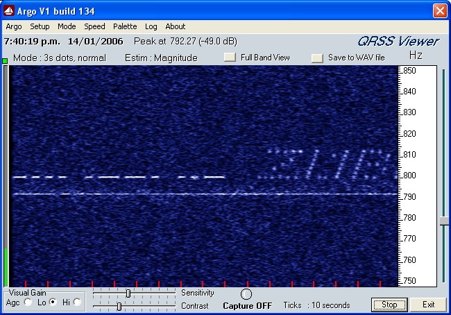
The first successful and confirmed transmission was on 15 Jan 2006 on 181.400kHz. At two independent stations in the Wellington area (500km range) the signal was clearly audible and identifiable. Signals were copyable even before dark (see picture), and tended to be stronger early in the evening. In the picture you see 'BPU' sent in QRSS3, followed by part of my callsign in QRSS3 compatible Sequential MT-Hell. The ARGO setting was 3-sec NORMAL (should have been SLOW), the receiver on USB, tuned 800Hz low (180.6kHz). The weak carrier below the signal is apparently power-line communications leakage. (Thanks to Bob ZL2CA for the picture).
The power level at the time of the picture was about 200W output. Later in the evening the power output was increased to 500W, still limited by adverse SWR. A good start!
19 Jan 2006
Made a very successful debut on the ZL LF net! Was copied by all stations in the 10pm round, but only by the Wellington stations in the 9pm (twilight) round.
Because of a short-term combiner problem, I was only running 250W output, but the SWR was good and the signal report was RST 569 from ZL4OL in the deep south (about 1000km away).
The fortnightly ZL Net takes the form of sequential North-to-South two-minute transmissions on 181.400kHz, coordinated via an 80m SSB net. Two runs are made, at 9pm and again at 10pm. In
summer the sun is still shining in the south for the 9pm test.
After the net I ran the transmitter with its beacon message, and Mike ZL4OL captured a very strong 3-sec SLOW
Argo picture. This is obviously E-layer sky wave propagation. Thanks to Mike for the picture.
The commissioning and use of the transmitter, along with design notes and suggestions, are now covered by the MENU ITEMS at the top and bottom of this page.
Please remember that this is an Amateur Conversion of the SA SC1000 transmitter, and the sentiments, suggestions, criticisms and comments here are in no way related to, or have any
bearing on, the original commercial use of this impressive transmitter. Errors, misunderstandings and omissions are all my fault, and should not reflect on the manufacturer
in any way. The manufacturer has not provided me with any information other than that on their web site and in the manual.
Specifications
Transmitter Overview
Detailed Description
Commissioning the TX
Build your Own
ZL1BPU LF Station
Copyright � M. Greenman 1997-2005.
All rights reserved. Contact the author before using any of this material.
HOME