
Some Keyer Circuits
The Zeekey: In 1967 Chet Opal published the first digital keyer design using logic chips in QST, called the “Micro-TO” keyer. The ARRL handbook published an RTL(Resistor-Transistor Logic) version in 1972. This formed correctly ratioed, self-completing elements, but wasn’t iambic.
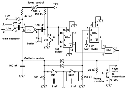
RTL rapidly became obsolete. In 1979 I implemented the same logic in the Zeekey, at right, using two locally available CMOS chips. This became popular in ZL, and was widely built.
However, The first “keyer on a chip”, the 20-pin, Curtis 8043 had already been designed and marketed by Jack Curtis in 1973.

In 1950, OZ7BO published the first reliable electronic keyer circuit, at right. Speed, weight and element
length ratio had separate, interacting adjustments.
The original used 6SN7 triodes, and drew
40 - 100 mA from the 250V supply, all of which appeared across the “dah” paddle. Two relays, with windings and contacts marked “A” and “B” were required. Many built it.
It was acclaimed for the quality of the code it
produced, superior to that of mechanical bugs.
Around 1955, Jim W9TO designed the first truly digital keyer. He passed hand-drawn schematics around to friends, but never published it. I re-drew the schematic from a faded copy sent to me by Peter, ZL4GU, who used it for 15 years.
The clock at left was a cross-coupled multivibrator. The divide by 2 (right hand) stage and some logic produced a dah 3 times longer than the dit.


Steve, K1EL, produces a variety of single chip keyers, with software based on my algorithms, and sells chips alone or installed in complete keyers.
The K12 chip, his latest, can be ordered from his website (Google on K1EL).
This implements a speaker oscillator and monitor, 6 pre-loadable messages, speed change up/down by paddle, selectable auto word spacing insertion, as in the ATtiny25.

Two other minimal versions of the ATtiny25 keyer. The left-hand one changes the speed with a traditional potentiometer.
The right-hand version shows modified connections to pins 6 and 7 (others the same) eliminating the potentiometer, with speed change implemented only with a pushbutton and the paddle. This is very convenient for portable operation.

This is what I consider the best of the early electronic keyers. This one appeared in 1960 era ARRL Handbooks. It used two 12AU7 triodes, though other types worked too. I used 6SN7s.
Speed was set by adjusting the frequency of the blocking oscillator at top left with the “speed” pot. This generated a fast-rising, slow-falling triangle wave. The “ratio” pot set the relative dit/dah lengths. The “weight” control adjusted the threshold of a Schmitt trigger, setting the inter-element gap. Elements were self-completing, but non-iambic.
This became quite popular. Easier to set up than a mechanical bug, it maintained relative element lengths pretty well over a speed ratio of about 2:1.
I Described it in my March/April 2014 Morseman column.
in 2007 Bryan, ZL1NI, produced the ATtiny25 Keyer, another single-chip device using an 8pin Atmel microcontroller.
For a minimal configuration, the “speed” pot can be omitted, and speed changed incrementally up/down using the dah/dit paddles, when the “Speed Adjust” button is pressed. It needs 2 AAA cells, which last a long time
The PCB with all components installed and tested can still be obtained from him at his call-book address for $14, including postage.

Below: The famous ACCUkeyer!
This is a CMOS version, first published in 73 mag, august 1975.
The original TTL version was published by Garret, in 1973, in QST magazine.
This keyer was the first to implement an optional “Auto-space” circuit, see the switch at the output of IC6.
I built both the original and CMOS versions.
It’s not easy to follow how it works from the diagram. Probably many thousands were built.