CTHA Antenna 2nd part
In the previous part I have described how the CTHA antenna do not change very much if we put a short circuit between the two helices in the point opposite to the feeding one.
This made me think that right and left half circumferences could be separated just connecting the two helices in those points.
So actually the CTHA could be interpreted as two CADUCEUS COILS (as named by J.Naudin http://www.jlnlabs.org/ http://jnaudin.free.fr/ ), fed in parallel shaped as half hoop.
By the way I measured the inductance of the CTHA at the feeding point: it is 2.245 µH without the short circuit and 2.246 µH with the short in place: practically the same very low value.
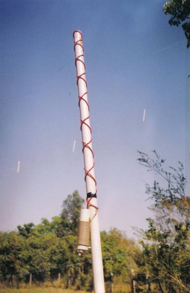
Not having at hand enough wire I made a single caduceus coil:
This has at the feeding point 2.73 µH.
With the 4:1 Balun shown in the photo I have got the following resonances:
|
16.695 MHz |
1.5 SWR |
|
24.775 |
1.0 |
|
28.165 |
1.0 |
|
31.680 |
1.0 |
|
35.850 |
1.0 |
|
40.370 |
1.0 |
|
43.740 |
1.0 |
|
47.171 |
1.1 |
|
50.460 |
1.3 |
|
54.565 |
1.0 |
|
57.375 |
1.3 |
|
60.000 |
1.0 |
This could be named also Counterwound Monopole Helical Antenna CMHA.
The straightened CTHA can be named: Counterwound Dipole Helical Antenna or CDHA
(that they are antennas it is just an hypothesis to be demonstrated !)
Really I had to investigate more the cause of all these resonances !!
This is my actual setup

The two antenna tuners are bypassed; so the linear amplifier. The long RG58 cable rolled between the first SWR Meter and the small antenna tuner is there as a choker. In fact the IC-706 had the tendency to self oscillate in the 18 MHz band, especially when the small tuner was properly set to match the Linear Amplifier. The chocker used to reduce the problem.
My first test was to replace the RG58 cable (red in the picture) with a shorter RG8 one.
Not much change: I still had the many resonances.
Here they are !
|
23.825 MHz |
1.4 |
|
26.455 |
1.1 |
|
29.680 |
1.0 |
|
32.650 |
1.0 |
|
36.340 |
1.1 |
|
40.065 |
1.1 |
|
42.980 |
1.3 |
|
46.280 |
1.0 |
|
48.950 |
1.0 |
|
51.400 |
1.0 |
|
53.935 |
1.0 |
|
56.490 |
1.3 |
|
58.975 |
1.0 |
I noticed that the Revex SWR meter was giving practically the same values as the internal SWR meter of the IC-706, but the SWR meter at the output of the linear amplifier was giving a much higher value when the other two were measuring SWR 1.0 !!
So I moved the cable coming from the antenna directly to the output of the Revex SWR Meter. Now the change was drastic !
The CTHA with the balun but without short circuit, was showing an SWR of about 2 between 56.0 and 57.5 MHz;
1.8 at 56.906
2.1 at 130.5
1.1 at 138.355
1.0 at 140.895
And an SWR <= 1.2 in the range 137.180 …142.895 MHz
With the short circuit in place the usable range was a little bit wider:
SWR <= 1.2 between 137.015 and 143.215 MHz with a minimum of 1.0 at 138.230 MHz.
Then I removed the balun and had the following minima:
Without short circuit:
|
87.130 MHZ |
3 |
|
97.140 |
2 |
|
139.900 |
4 |
|
148.200 |
2.2 |
|
155.080 |
2.5 |
With the short circuit:
|
154.750 MHz |
2.2 |
|
147.965 |
2.2 |
|
139.750 |
4 |
|
130.140 |
5 |
Definitely the 4:1 balun is useful !
So, I know now the cause of the resonances but not the reason !
I made the same measures with the “CMHA” or Caduceus Coil
Without balun:
|
135.475 MHz |
2.5 |
|
142.545 |
4 |
With balun:
|
51.137 MHz |
1.0 |
|
137.310 |
1.0 |
|
141.525 |
1.0 |
Being the SWR <=1.5 in the range 50.000 … 52.120 MHz
The length of the two helices of the CMHA is 153 cm each; the plastic tube has 4 cm of diameter and the total length is 91 cm.
Pino Zollo ZP4KFX 5th November 2006