CTHA
Antenna
Since some time I wanted try
the CTHA antenna, so I did look for some infos in
Internet.
Not having found any clear information about how design a CTHA for a
specific band I decided to build one using the materials available in the shack
just to investigate its behaviour so to be able to scale it to some radio
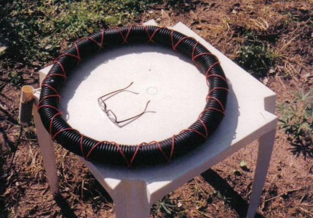
amateur band. With a flexible 7cm diameter tube I managed to
build a toroid with a diameter of 60cm. On it I did wound 2 helix of 15 loop
counter-wound.
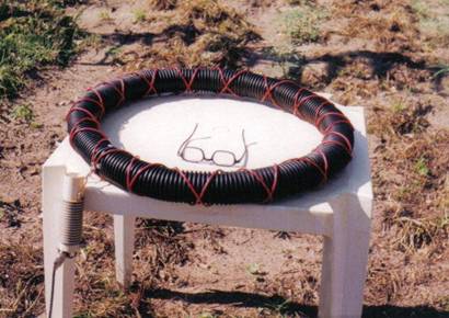
I did put the CTHA on a plastic table in the garden connected with a
RG58 cable and I did start to measure SWR using as source my IC-706 MKII at 10W and the SWR
meter Revex W570.
I want to share the results of my investigation with colleagues
I was looking for
three resonances as described in the article “A Study of the CTHA Based
on Analytical Models” by Douglas B. Miron, but with my surprise I found a lot of resonances with SWR exactly equal
1. Here is the list:
|
23.920 |
|
27.510 |
|
31.115 |
|
35.215 |
|
39.675 |
|
43.105 |
|
46.560 |
|
51.970 |
|
55.200 |
|
58.600 |
|
70.220 |
|
72.020 |
|
74.380 |
|
77.320 |
|
81.460 |
|
84.040 |
|
85.920 |
|
88.380 |
|
……
the IC706 do not transmit much in FM band |
|
139.280 |
|
146.360 |
And maybe others.
Besides I noted that SWR is <=2 in the range 23.960 MHz to 8.880 MHz.
I wanted check if it is
possible to tune the CTHA to a different frequency so I did connect a small variable
capacitor between the cross of the two helices in the position just
diametrically opposite to the feeding point. I have found that the resonances
change their values. Here is a short list limited up to 60 MHz.
|
17.150 |
|
19.025 SWR=1.2 |
|
23.865 |
|
27.295 |
|
31.250 |
|
35.600 |
|
40.305 |
|
43.800 |
|
47.615 |
|
50.800 |
|
54.320 |
|
57.825 SWR=1.5 |
Where not stated SWR is
exactly 1 !!
In the zone 15.940 MHz to 20.985 MHz the SWR is <= 1.5 with
oscillations.
The resonances are quit wide: just an example: at 27.295 MHz the SWR is
<= 1.5 between 26.590MHz and 28.220 MHz, actually a band usable of 1.630MHz !!
Just for fun I did replace the capacitor with a
short-circuit. Not a great change ! here is the list of resonances with the short-circuit.
|
16.950 |
|
18.935 |
|
19.115 |
|
23.895 |
|
27.395 |
|
31.265 |
|
35.660 |
|
40.325 |
|
43.880 |
|
47.695 |
|
50.810 |
|
54.230 |
|
57.915 SWR=1.4 |
I had at hand an RG58 cable of 1.6m with connectors so I did insert it
to make the total cable a little bit longer. Living the
short-circuit in place here is the list of the new resonances:
|
22.615 |
|
25.690 |
|
29.395 |
|
32.790 |
|
36.790 |
|
40.780 |
|
44.000 |
|
47.015 |
|
49.715 |
|
52.280 |
|
55.430 |
|
58.560 |
Being SWR <=2 between 11.850MHz and 24.025MHz
It seems that the cable is participating to the value of resonances, but
SWR is always just 1 !! this
did puzzle me very much.
I have lifted the antenna on a wooden post and put it in vertical
position getting some frequency shift of resonances.
I tried to do some numerology to correlate resonances with the antenna
measures, but without any success.
A mad idea was tormenting me:
I had the first time this idea when adjusting the 40m magnetic loop shown
elsewhere on this site.
When used in the exact resonance frequency the antenna is “willing
to transmit” with violence !!
I was using a power supply for the IC-706 made of two switching PC power
supplies paralleled and modified to give 13.8V. The magnetic loop was un the roof of my pick-up and the IC-706 and the power
supply was un the floor at about
Coming back to the CTHA, I was thinking that at the resonances the
antenna is so willing to transmit that, whichever is the Z of the cable, the
reflected power is ZERO because it is all transmitted, giving an SWR exactly 1.
To verify this mad idea I did insert between the CTHA and the feeding
cable a BALUN 4:1 that I had at hand, previously used for a folded dipole.
The idea was that if the impedance of the CTHA is 50 Ohm, putting the
BALUN 4:1 the SWR should rise to 4 at least.
My mad idea has been verified !!! SWR at resonances is still 1
!! Here is the list of frequencies a little bit moved. (Short-circuit on
the opposite side in place)
|
18.880 |
|
24.660 |
|
28.185 |
|
31.765 |
|
35.900 |
|
40.290 |
|
43.935 |
|
47.535 |
|
50.595 |
|
53.545 |
|
59.510 |
With SWR <=2 between 10.880MHz and 22.955MHz.
Further more now I have the following SWR in amateur bands:
20m 14.000 1.8
14.350
1.7
17m 18.068 1.4
18.168
1.4
15m 21.000 1.4
21.450 1.2
12m 24.880 1.1
24.990
1.2
10m 28.000 1.0
28.500
1.2
29.0
1.5
6m
50.000 1.3
54.0
1.2 with two
minima in the middle.
Isn’t it astonishing ???
Well I do not know if it is an antenna or a dummy load but at least I do
not need an antenna tuner !
Before putting the 1:4 BALUN I made a QSO with LU3DDH at 28.330MHz, but
propagation was very bad.
I have got the idea that the best efficiency is between 70 and 50 MHz
but I am not sure of this.
I nice test would be the following:
Put two equal antennas 100m apart, one with a TX and the other with an
RX and plot the received field in function of the frequency. With such a setup
should be evident where the antennas work better even if it is not possible to
measure the real efficiency. I am sorry because I can not do this experiment
because I do not have a second wideband RX an a friend
to help me.
One more observation:
During the first day of tests, with the antenna horizontal at 70cm over
ground on a plastic table I happened to tune at 52.765MHz a
sub-harmonic of a local FM station (Radio San Pedro FM 105.5) at about
The following day, when the antenna was vertical tied to a pole, I
wanted listen to some music, so tuned the RX to 52.765MHz…..but nothing
at all !!
“Strange”, I thought, “maybe it is not
transmitting”….so just by accident I switched to an other antenna
and the signal appeared !! S9+++
Never seen before such a big separations between orthogonal polarizations !!!!
So, I hope that this short note will stimulate further studies on this
strange antenna.
Why it is bewaring in such a wide band mode ?
Which relation between the physical dimensions and the resonances ?
How to optimize the CTHA for HAM bands ?
Which efficiency may be expected for mobile use on 40m and 80m ?
73 de
Pino ZP4KFX 28th July
2006
(modified on 4th November 2006)