- Recycled Radios -
The ZL1BPU
7727 Linear Amplifier
Making a 100W PEP linear in one weekend!
Introduction
At some time or another, most Amateurs have tried building their own simple HF transmitters. For some it is an interesting learning experience, for others a matter of frustration, while a few die-hards consider that there is no satisfaction like that of operating your own gear - and best of all, proudly telling the other guy that your gear is 'home brew'!
Unfortunately many of the designs around are QRP, and those that offer higher power involve finding expensive transistors and hard-to-find components such as double-hole ferrite chokes, ferrite beads, high voltage capacitors and powdered iron toroidal cores. Finding suitable
transistors for the steps from 100mW to 10W is also difficult.
Even those with no interest in building transmitters, but have a keen interest in antenna design and adjustment will be interested in this project. It consists of a 'bullet-proof' 100W linear amplifier with sufficient gain to operate at full output driven from a signal generator or sweep generator (don't use the sweep generator with an antenna connected unless the band is dead!
The best part about this project is that you can make the linear with simple hand tools, limited electronics skills, a few junk-box components, a recycled radio, and it only takes about two evenings to complete!
The Codan 7727
This SSB radio was designed in the late 70's, and was popular for many years as a commercial mobile radio for forestry, mining, government departments etc. In latter years, as the commercial users moved to trunked radio or cellular phones, these radios were used for volunteer organizations, off-roaders (especially in Australia) and Amateur communications, especially for car rallies. Now, there are few people interested in these simple radios, mostly because they are crystal controlled.
The 7727 is a single-conversion design with a 1650kHz IF. Operating frequency was selected by a channel switch, which changed crystals and switched in different filters for each position of the switch. The performance of the radio was very good for the time, and the units were very stable, robust and reliable.
One of the problems with restoring life to a 7727 is that the coils in the front end filter are now impossible to find, and very difficult to replicate. These coils are also easily damaged, and once the radio has no viable coils, what can you do with it? Well, since you
don't need the old exciter board, make the transceiver into a linear for your QRP rig!
Where to Find a 7727
If you don't have a suitable Codan 7727 in your junk collection, check with your local AREC leader and commercial radio service company.
Wait for the next junk sale or swap-meet. Without coils and crystals, these units can be picked up for $30 or less.
Other units can have similar treatment (e.g. the Codan 6801 Mk 2, 8121 and various Ambassador models), but the conversion to be described is specific to the 7727.
The Power Amp
The PA section of the 7727 is completely self-contained, consisting of a circuit board connected to a heavy heat plate and a modest heatsink on the back of the case. The design lends itself readily to adaptation. The PA section consists of a controlled gain ALC amplifier, a class A amplifier, a class AB push-pull 5W driver, which operates a class AB push-pull final stage with 100W PEP capability. The PA section also includes SWR measurement and protection circuitry, along with ALC to control the output (keep it linear) and protect the amplifier from damage.
The whole amplifier is a broadband design, and capable of reasonable power output from 200kHz to at least 19Mhz (see power graph). The gain is about 65dB, reasonably flat from 1.5 to 12MHz (see gain graph), with reduced gain from 200kHz to above 19MHz. What makes the unit especially useful is the combination of gain and built-in ALC - there is more than enough gain to provide full output from a balanced mixer (say a QRP rig) or even a signal generator - in fact 20mV RMS (-24dBm, -35dBV) is quite enough. The ALC holds CW power at 50W from about 25mV input (see ALC graph).

Power, Gain and ALC Performance Graphs (Click on a graph to view in detail)
The way the 7727 was designed, conversion to a linear amplifier is very simple. If all you need is an amp for your QRP rig, and don't need change-over switching or PTT control, you can make the necessary adaptations without even warming up a soldering iron! For a full
conversion, you only need to add these simple circuits:
- A PTT control circuit (also acts as CW key if you need it)
- An additional small relay to switch the receiver output.
With these simple changes the linear will operate in the same manner as a typical VHF amplifier, feeding the antenna signal back to the receiver on the same cable that takes drive from the exciter. You could also add an RF-sensing circuit to avoid the need for PTT connection.
It's too much effort to cut the case down to suit just the amplifier, or to make a special cabinet, so just put up with having a bigger box than you need.
Dismantling
Get your side-cutters and spanner ready! The first thing to do is disconnect a few things. Remove the covers. Undo the screws holding the speaker to the front panel, and remove the speaker, grille, and all the knobs and nuts from the controls on the front panel. Pull back and remove the Clarifier, Volume, LSB/USB/Tune switch and the Noise Limiter switch. In most cases you can simply leave them dangling inside the radio - nobody will know! Leave the Channel switch intact.
Very carefully unscrew the lamps from the front panel (from the rear), and unsolder the wires to remove them, pulling the lamps out the front. You will be reusing these and the Channel switch. Cut free the Mute switch, and rewire the power switch wires from the Volume control to this switch.
On the back of the cabinet (back left corner, at the bottom) you should find a blanking plug concealing a 12mm hole (if not, you'll need to carefully drill one). Lift the lugs from the inside and prize out the blanking plug. This hole is used for a threaded mount BNC connector, which will become the input connector. Make sure you add a ground lug under the nut on the inside. I used the insulated connector from an old network card, but a grounded connector will do just fine.
If you intend to use PTT to control the linear, fit another connector on the back for the purpose. I drilled a 7mm hole directly above the new BNC connector, and fitted a threaded mount phono connector.
On the top of the unit, disconnect ALL the plugs from the main circuit board. You won't be using this board at all. There's no real need to remove it, but you can if you wish. One of the plugs you disconnect has two coax cables laced together, and a four-pin brown socket. Thread this cable down through a convenient gap in the chassis and pull it over to the new BNC connector.
One more junk-box component is required - a small 12V change-over relay. Choose one with low operating current (coil resistance above 400 Ohm). Fit this in the back corner underneath, near the new BNC connector - see the photograph. Leave 3mm space between the relay and the side wall so the bottom panel will still fit. I stuck my relay down with thick double-sided tape. Wire the relay coil between 0V (on the end of the amplifier board, near the fuse), and the switched 12V line, at the left end of the driver power link, shown top left in the photo. The relay will then pull in when power is applied to the driver stages of the amplifier. Wire the CO (common) contact to the BNC connector, and the NC and NO contacts to the outer two pins of a 4-pin 2.54mm pitch pin connector. Connect the inner two pins to the ground lug on the BNC connector. Keep all these wires very short, and all up in the corner by the BNC connector. Plug the 4-pin brown connector into the new 4-pin plug connector. The coax with the identifying sleeve should connect to the normally closed (receive) contact. Check that the cables, connectors and relay don't foul the lower cover as it is replaced.
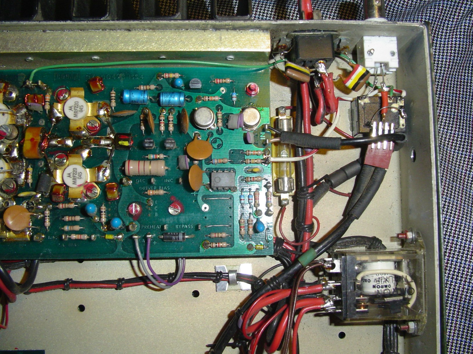
Fig. 1. Detailed view of Amplifier input (click on image for full-sized view)
Take great care with the wiring, as the amplifier has very high gain, and if your ground connections to the amplifier are poor,
relay isolation low or your screening is slack, the amp is sure to take off. Note that the amplifier is not grounded to the case.
Reassembly
Make a new front panel (use this art work) by printing the design onto strong paper with a laser printer, and facing it with library film or acetate sheet. (Another useful method is to print it direct to a laser copier transparency sheet, then back that with a coloured piece of card). The front panel will be held in place by the controls, and round the edge by the covers. Don't use glue or tape, as it eventually discolours the panel.
The best way to cut the holes in the new front panel is to temporarily hold it in place with sticky tape, and cut around the appropriate holes with a fine sharp scalpel or modelling knife, using the edge of the metal front panel holes as a guide. Assemble the front panel and reinstall all the controls and knobs. The Channel switch becomes the low-pass filter BAND switch, the Mute switch becomes the POWER switch, and the Noise Limiter control is replaced with a 6.5mm phone plug, used as the KEY jack. Rat around in your junk box for a connector that fits the 12mm hole comfortably.
Unfortunately the amplifier is keyed to +12V to turn it on, rather than to 0V, as is conventional. You will need to build a simple keying stage using ugly construction (see Fig. 2). Find the pin on the amplifier board marked 'PTT' (near side left with the front of the radio facing you) and on this point construct the PTT keying transistor. Use a BC557 or BC327 or similar transistor (PNP). Connect the collector to the amplifier PTT pin via a 2k2 resistor
(not shown in the diagram below), the emitter to the nearby fuse-link (12V), and connect base to emitter via a further 2k2 resistor. Connect one end of a 10k resistor to the base as well. The other end of this resistor is the new key-to-ground PTT line. Wire this point to the tip contact of the KEY socket, and to the rear-panel PTT socket. Wire the sleeve contact of the KEY socket to the 0V of the amplifier board.
Fig. 2. PTT and keying stage
You may not realize it, but all the circuitry on the amplifier board is isolated from the case. Both amplifier input and output are transformer coupled, and grounded to the case, but everything else floats. This allows the radio to be used in positive earth vehicles, but is also a very good way to prevent feedback through ground loops, and one of the secrets of how this design remains stable with such high gain. However, you will need to make some DC connection between the 0V and the case, or the PTT circuit will not operate. The simplest way is to fit a 2.2k resistor between the 0V and the case, which you can do most readily at the power connector (not easy to see in the photo above, as it is under the connector). Alternatively, use an ungrounded phone jack or other connector for PTT, wire it in parallel with the KEY socket, and omit the 2.2k resistor.
Wire the TX lamp back to its original connections. The POWER lamp will need new wiring, back to the coil connections of the big relay on the under side. My lamp was broken, so I replaced it with a 3mm LED in the same holder, and connected a 1k resistor in series. With the original lamp, fit a 120 Ohm resistor in series.
How it Works
It will be helpful to read a copy of the
7727 Service Manual. You will have noticed during your modifications that there is another big relay (in the photo, Fig. 1, bottom right), which controls the DC power. It is now wired to your POWER switch, so it pulls in when DC power is applied and the POWER switch actuated. The coil has a diode in series, so if you connect the power backwards, the relay will not actuate, the POWER lamp will not illuminate, and the amplifier will be undamaged.
When the power relay actuates, it applies 12V to the final amplifier stage, and to a DC switch power transistor (and now our PTT circuit).
There are now two further relays, controlled by the PTT circuit. When the PTT line is grounded or keyed, the new PNP transistor conducts, pulling high the original PTT line, which enables the DC switch transistor, applying power to all the other parts of the amplifier, and actuating the two relays. One is our new relay, which switches the input connector between the receiver bypass coax cable and the amplifier input. The other is the antenna relay on the amplifier board, which disconnects the receiver bypass coax cable and connects the amplifier output to the antenna.
The relay you added allows the transmitter drive and receiver signal to share the BNC socket for connection to the exciter. It provides isolation in both directions. You can't just connect the two cables together at the connector, as the antenna relay leakage will turn the amplifier into a high powered signal generator!
These small relays (and the whole amplifier) operate quite quickly, so you could operate them from an RF-powered VOX circuit. However, the drive level required to operate the VOX would be much more than that required to operate the amplifier. The amplifier will certainly key for CW very nicely. Apply drive (even just a VFO) and away you go! The relays clatter a bit, but the keying is clean.
The original channel switch (now the BAND switch) also selected low pass filters used to keep the output signal clean by removing harmonics. These filters were well designed, and have quite sharp cutoff. The ranges are 1.8 - 3MHz, 3 - 4.6MHz, 4.6 - 7Mhz and 7 - 11 MHz. I later added another one for 11 - 15MHz, using a simple 5-pole PI design. It is best to rearrange the wiring of the two related wafers of the BAND switch so that the filters are selected in ascending order, as you will see from the front panel view. If you wished, you could label the switch positions '160m', '80m', '40m' and '30m'.
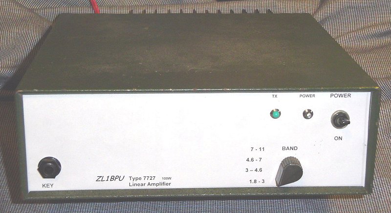
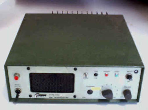
Fig. 3. Front View of Amplifier (click on image for full-sized view)
The filters are connected so that on the lower bands the higher band filters are still in circuit, which adds extra performance.
There's also an extra filter which is used during receive. This is a high-pass filter, which attenuates the broadcast band to limit intermodulation. Don't be surprised if LF reception through the amplifier is poor!
The TX lamp is wired in series with the bias regulator for the PA final stage. As the output power increases, the bias current increases, and the lamp glows brighter. On AM it may glow brightly and dim as you speak - it depends on the characteristics of your exciter.
Why are there no meters on the amplifier? Because none are needed! All you need is a good SWR bridge in series with your antenna tuner, and then adjust for best SWR. In fact, if you don't have an SWR meter, you can simply adjust the tuner for maximum brightness of the TX lamp and be confident that tuning is good. The amplifier has several feedback signals to the ALC system (output voltage, PA current, reflected power and forward power), and unless the conditions are correct, the ALC will not allow the PA to produce much power, so simply adjusting for maximum brightness is enough. The comprehensive ALC system also ensures that the amplifier is well protected from overload, excessive voltage or a disconnected antenna.
Operating
You can't just drive this high-gain amplifier with any old signal. It will operate from just about any source, but you must first set the correct drive level. Over-driving could cause damage, and will certainly cause excessive distortion. First, connect the amplifier output to a 50 Ohm dummy load (rated for 20W continuous use or higher), apply 13.8V DC power (up to 20A drawn), and connect the exciter you plan to use to the input via a switched attenuator (even a 100 Ohm pot may do). Never use more than about 1mW drive. You may prefer to take the drive from a lower power stage in the exciter.
Watching the SWR meter power output, key the amplifier and keep increasing the power by increasing the drive until you reach about 50W indicated. Any more drive will not increase the output, just increase the distortion and noise. Remove the drive (but keep the amplifier keyed) and check that there is no output.
If you can, use a two-tone generator, and check the output with an oscilloscope or spectrum analyser. On the oscilloscope you should see nearly 200V p-p (100W PEP) with minimal flattening of the peaks, and the spectrum analyser should show minimal intermodulation products. Check other modes (CW, SSB) and adjust the attenuator for the best compromise in linearity. You can afford slight overdrive on CW. I found that my 10mW QRP exciter (Kenwood TKM-707) produced just enough drive from the low power stages that I could operate it without an attenuator, and I adjusted the internal drive control to set the optimum level.
If you plan to use the amplifier just with one QRP transceiver, fit the appropriate attenuator permanently inside the unit at the input to the amplifier board. That way the receiver won't be affected, and it can also help keep the amplifier stable.
When you go on the air, tune up into the antenna by driving the amplifier in CW mode (unmodulated AM would do), and adjust the antenna tuner for maximum power output and minimum SWR. Then adjust the drive to give you the power output you want for the conditions. Finally, switch to the mode to be used and check output. On CW you should achieve 50W carrier, on AM the same, but it may drop off as you speak. (If your AM rig has real high level (upward) modulation, reduce the drive for 30W carrier output). On SSB, the amplifier gives the impression of being short of drive, indicating barely 20W, although you can talk it up higher with a compressor. Be assured however that the amplifier will be producing 100W PEP, which you can check with an oscilloscope or an SWR meter with PEP mode.
When operating digital modes, (especially PSK31 and other modes requiring high linearity), keep the output power down to 20W average or below. If you wish to, fit a meter on the front panel where the speaker was. Arrange it to measure the voltage on the ALC control point (IC2 pin 7), and for PSK31 adjust the audio drive (sound card output) so that the ALC nearly starts to activate. Any more, and the ALC circuit, which is designed for voice characteristics, will introduce its own distortion on the signal.
While the unit will operate right down to 200kHz, bear in mind that the low pass filters are not effective below 1.8MHz. By the same token, when operating
the amplifier at higher frequencies, always use the correct low pass filter. If the filter cutoff chosen is too low, the amplifier will see a serious mismatch. If it is too high, harmonic suppression will be compromised. If you look at the power graph,
you'll see that the filters are nicely arranged for 160m (2 - 3MHz), 80m (3 - 4.6MHz), 40m (4.6 - 7MHz) and 30m (7 - 11MHz).
My added filter extends the
top end to include 20m (11 - 16MHz), but much more drive is required. The filter switching is quite clever - the lower you go, the more filters switched it - the higher frequency filters are still in use. If you add your own 11 - 16MHz filter, put it in the input coax to the 'Band' switch, so it's in circuit all the time. You can of course use an external filter (in the antenna lead).
For Non-Solderers
If you study the BNC connector off an old computer card, you'll find that the connector has two pins soldered into the board. Just cut these off close to the board, and wrench the connector off its mounting pins. When you fit the rear-panel socket, just plug the brown 4-pin connector directly onto the pins of this socket! (Forget the relay stuff and the PTT circuit). You might have to go without the POWER lamp, but the TX lamp can be left connected (fit your new front panel over the lamp). Don't fit the toggle switch as the POWER switch, just leave the volume control in place, and rotate that to use the on-off switch.
You'll need to arrange some other way to key the transmitter (for example, key the exciter) and arrange TX/RX changeover, but you can at least turn the amplifier on and off with the POWER (volume control) switch. Not a soldering iron in sight!
Performance
When adapted carefully, the amplifier is very stable, very forgiving, and very easy to use. It may lack the punch of some 100W commercial Amateur transceivers, but you will find the signal is very clean. Although originally rated for 2 - 16Mhz, it works over a wider range given sufficient drive. The two-tone output is 100W PEP up to 40m and beyond, with CW output of 50W from 400kHz to over 19MHz.
The gain of the amplifier is about 65dB, so you can even drive it directly from a VFO or frequency synthesizer. It requires only 25mV RMS drive. The amplifier draws about 11A from the DC supply to generate a 100W PEP two-tone signal. On voice the current averages about 5A. The signal sounds really good on air.
Heatsinking is adequate for normal SSB and CW operation, but for extended use on digital modes, it would be helpful to add a small 12V fan to the heatsink. This could be powered from the output of the power relay, and so switch off when power is removed. Best of all, find a variable speed computer fan with a built-in thermistor. The prototype ZL1BPU 7727 Amplifier operates continuously for many hours at a time with 20W output and fan cooling.
Copyright � Murray Greenman 1997-2005.
All rights reserved. Contact the author before using any of this material.