Here are some undocumented or unfinished projects
 Raspberry Pi and SDR
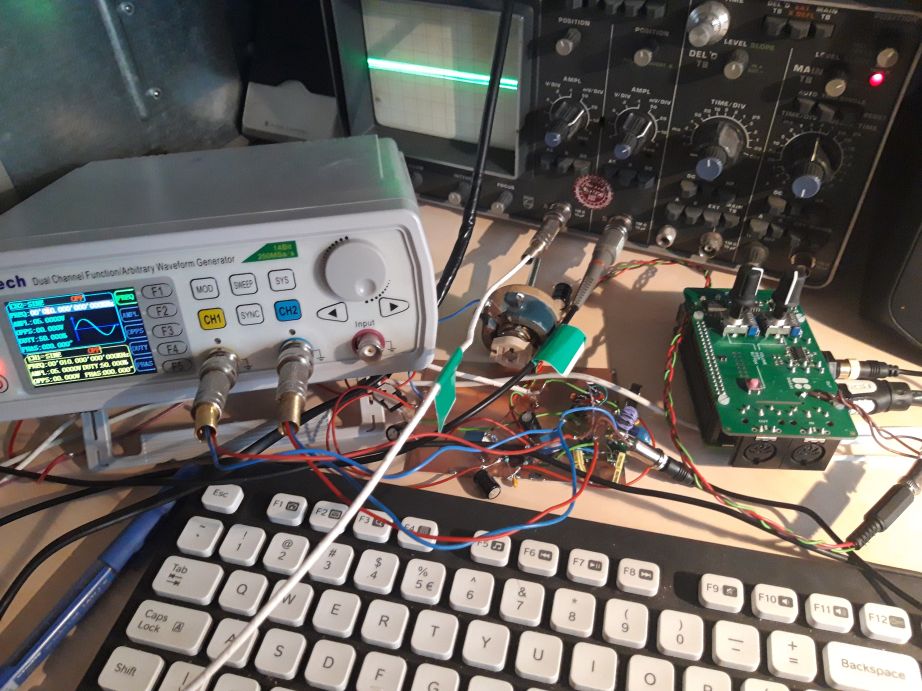
This is a zoom FFT setup with a Raspberry Pi and a 24bit/192kHz audio codec cip. Between the signal generator and the Pi board there is a quadrature sampling detector with 2 FST3157 analog switches. The I and Q signals are amplified with an NE5532 and feed to a PCM1804 codec. This codec is supported by ALSA. The big potentiometer is just a lazy trick to create a dual power supply since NE5532 is not rail to rail.
To my surprise I couldn’t find a suitable graphic library. Again I had the impression that in Linux world the programming effort is diluted in many redundant pieces of software. Some libraries like OpenGl are very complex for what I need. Others that were simple to use like RayLib wasted around 30% of CPU load after initialization even without drawing a single pixel. The ones that were simple and efficient lead you to dependencies hell. So after some frustration I decided to draw directly in frame buffer. Anyway I needed only pixel level control, no fancy effects. There is a great tutorial here: Linux low level graphics
DSP proved to be a paradise for experimentation. This was one of the most exciting things I ever did. Many nights I filled the house with single tone noises trying to fix the Hilbert transform to cancel one sideband. There is plenty of power in Raspberry Pi 3 to handle two 192kHz/24bit audio streams and to perform an FFT with 8192 bins, a serious FIR filter, display the spectrum and output the processed signal. Playing with threads and Linux scheduler modes was fun. Raspberry Pi cores can be all put to work in the same time.
Direct conversion transceiver
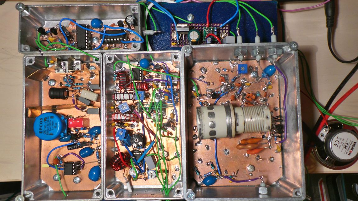
This is an example of what happen when a simple idea is ruined by adding just a few new features. The original plan was to build a simple mono band direct conversion (DSB) transceiver that will be portable and low power. I stole many ideas from the great book “Experimental methods in RF design”.
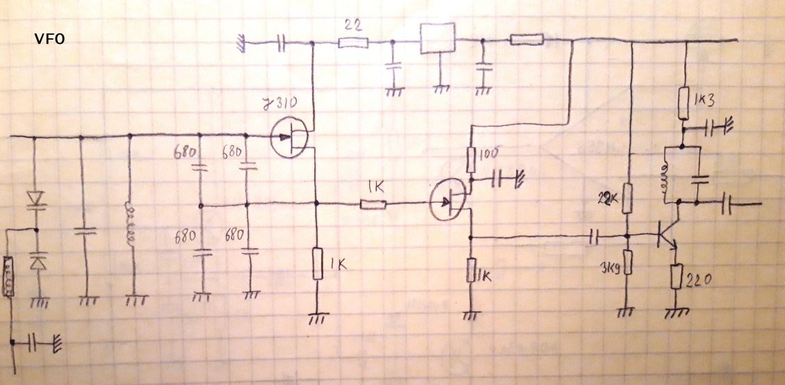
Even if I used an AD9854 DDS in the past I wanted to use an analog VFO. Also because I had just acquired that fancy white ceramic coil that you can see in the picture. The windings are made from a strip of silver deposited directly on the ceramic support. This was promising a pretty stable VFO. I added a lot of varicap diodes in parallel to keep a high Q factor and use only silver mica capacitors in critical parts. As a result the stability in the 3.5-3.8MHz interval was very good.
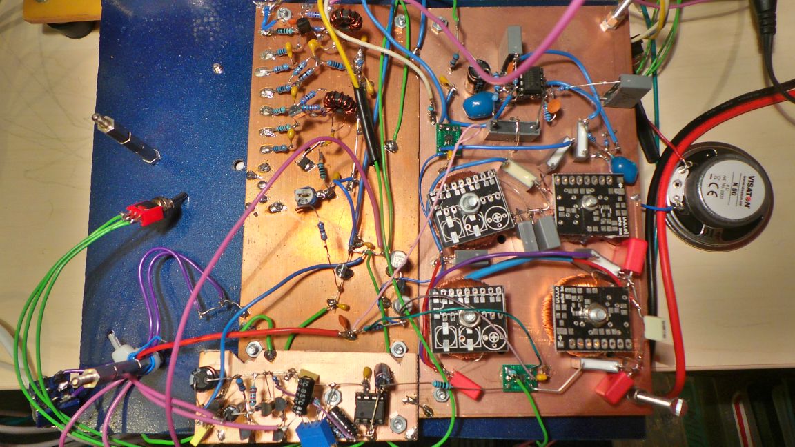
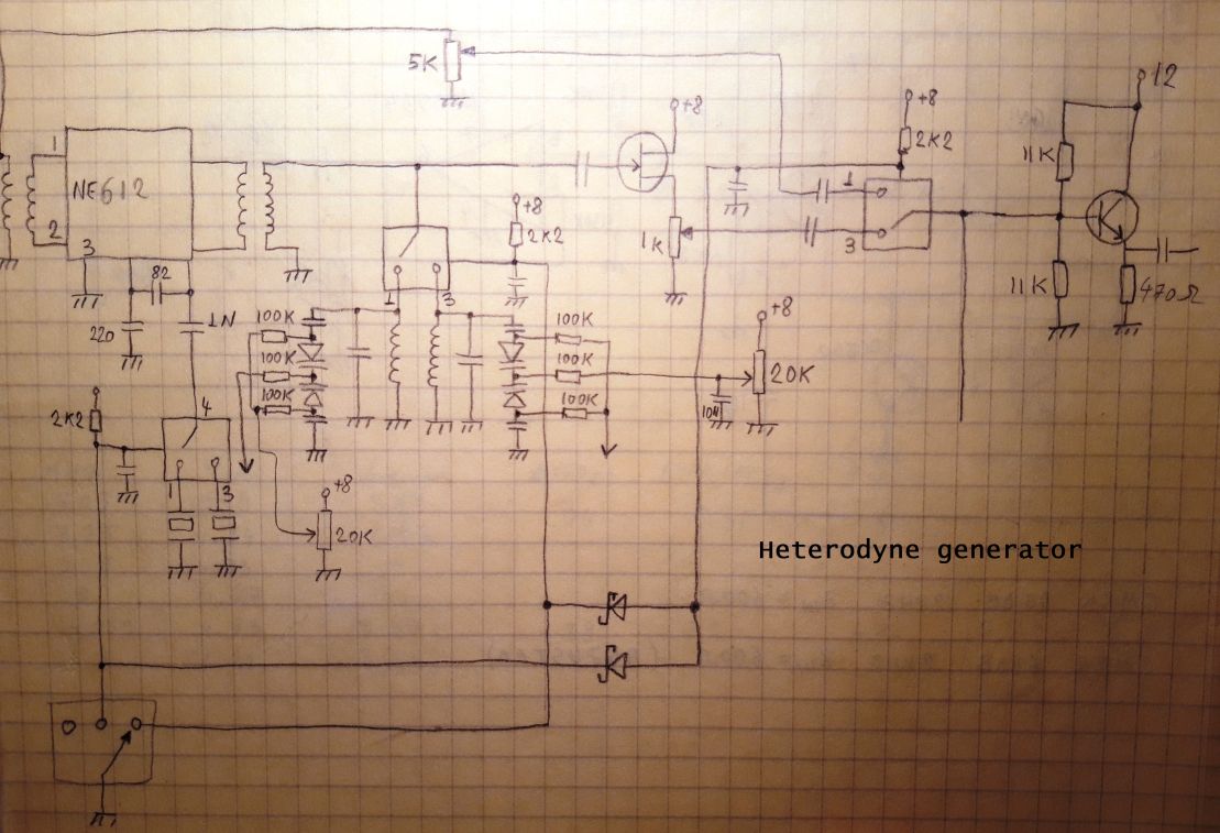
At this point I started to think that it would not be a big deal to make it a 3 band transceiver. I found 2 crystals that would allow me to translate the VFO to 7 and 14MHz using the heterodyne method. So the next circuit appeared. The idea is pretty simple. The VFO signal enters an NE612. The two crystals are using the NE612’s oscillator. At the output of the mixer I added 2 band pass filter. Now things began to be complicated. I discovered that it was difficult to keep the amplitude constant and in the same time to isolate the desired frequency. That is why the filters are tuned with a voltage that is tracking the VFO tuning voltage. There are some AOs than are doing this. The whole thing was a big pain in the ass to setup. But in the end I got 3 variable frequencies with very good stability.
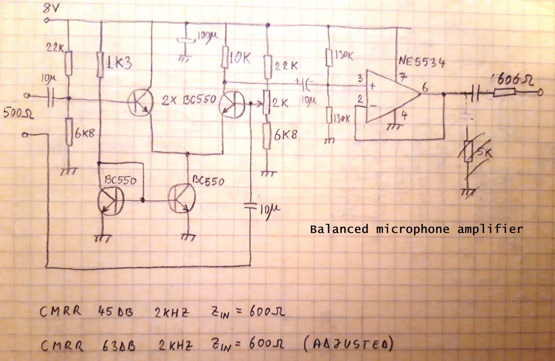
Next I built the microphone amplifier. It is a balanced type with discrete transistors. Of course it doesn’t need to be balanced or to be built with transistors but why not have some fun? It was also nice to tune it to get the maximum CMMR.
The RX mixer is a level 17 SRA-3H Minicircuits diode type. 6 inverting gates are connected in parallel to drive it with enough current. The VFO is squared with a CD4046. This IC, among other things, can generate symmetric square waves from a low amplitude sine wave.
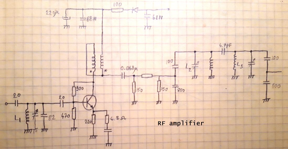
After the mixer there is a passive diplexer and a low noise amplifier. Both are inspired from EMRFD book. The TX power was around 50mW. Enough to drive a 15W amplifier with one RD06HHF and two RD16HHF transistors. The audio quality was very good. Overall building this transceiver was fun but in the end I decided that the whole thing departed from the simple original idea so I let it unfinished.
High voltage power supply
I like to restore old tube transceivers and one of the biggest problem I have is the lack of an adequate power supply. This kind of transceivers used to have separate power supplies and they can be quite expensive because of the shipping cost (they are heavy). So after improvising every time with many transformers and variac just to get the right voltages I decided that something has to be done.
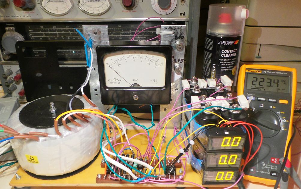
This is a test version of a universal supply that provides the following outputs: a low voltage and high current 6.3 or 12.6Vac for the heaters, 250-275Vdc at around 150-200mA for tubes, 570 to 800V at max 600mA for power amplifier and a negative voltage between -60 to -140V at 5-20mA for grid bias. This will cover the needs of my Collins KWM-2, Swan 350, Hallicrafters SR-160 and Drake TR4C.
I ordered a 500VA toroidal transformer for all high voltages and with 3 primary taps for 220, 230 and 240Vac. There are up to 35 volts variation of mains voltage here. All voltages are un-stabilized except the negative bias voltage.
The toroidal transformers have an inrush current much higher than the laminated core types. For example I have a 1:1 1.5kVA toroidal isolation transformer that blow the automatic circuit breaker in my home one in 5 times when I turn it on. Without a load. Another annoying thing about that transformer is that it has a few nF capacitance between the 2 windings. So is not quite an isolation transformer.
This 500VA transformer is smaller but still it causes the dimming of lights when I turn it on. High inrush current also complicate the fuse protection. My initial idea was to wire the primary circuit through a rotary switch. The first position is Off, the second connect the 220 tap through a 1K/5W resistor then the next 3 taps are for 220, 230, and 240 taps. This was good only for limiting the charging current for capacitors. But since the switch is a brake before make type (as it should be in this case) I still have shock when switching the taps. You can hear actually a short buzz.
Another problem was the choice of fuse for 800Vdc circuit. Original supplies have no fuse there. But they use ridiculous small capacitors in combination with chokes in the tens of mH range. I add in series 3 x 900uF/450V caps. Just because I had them. That is a lot of energy to discharge in case of a short circuit. A fuse for that voltage is pretty expensive, and large. I’m not sure how a regular 250V type fuse will behave.
I add 3 digital voltmeters to monitor the high voltages. Since I do a lot of debugging in these radios I want to know when caps are discharged. I found it intriguing the choice of bleeder resistors in some original power supplies. They dissipate up to 15-20W in some cases. In my case it drains 4W and discharges the 800V caps in 1 min.
The digital voltmeters caused a lot of problems because they each have a switching mode power supply inside. This ruined the reception in some bands, so I need to bypass them with a linear regulator
I love the big analog meters so I couldn’t waste the chance to put a big one here. It is a 100uA type with 2 intervals. I can be switched to measure current on the 800V or 275V circuit with 1A and 300mA range. The inertia of the indicating pointer is huge. It needs about 5 sec to return to 0 for example. So is pretty useless to estimate PEP power, but is very precise at measuring the idle current.