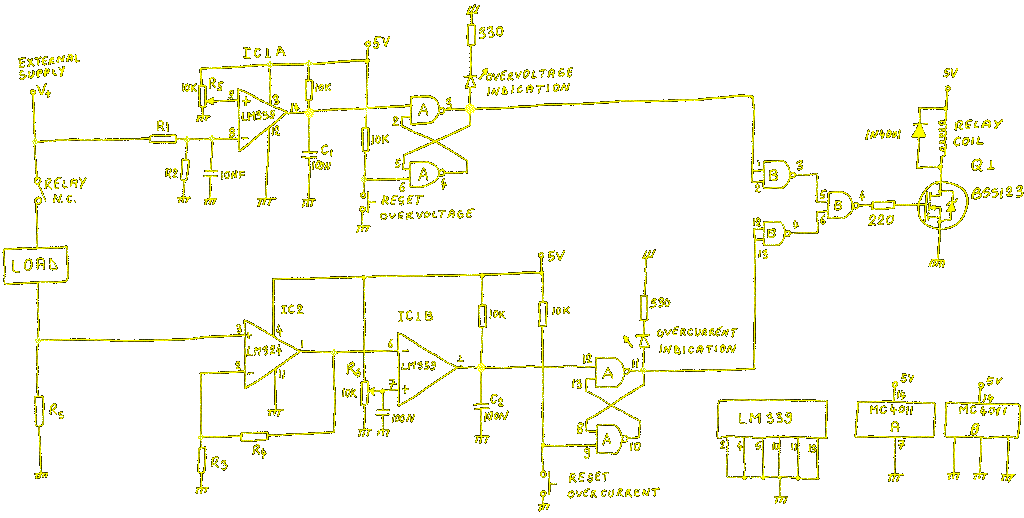
Circuit for over-voltage and over-current protection
Did you ever have expensive equipment connected to a dubious power supply? Few years ago I was in such a situation and I looked for a simple protection circuit to disconnect the supply in case of overvoltage or overcurrent events. In the end I came up with a circuit that turned out to be not so simple, but it worked. Its features are:
-Any value can be set for overvoltage and overcurrent threshold, just change the shunt and a resistive divider
-Load is disconnected with a relay for maximum flexibility
-Circuit use a separate power supply for reliable operation
-Separate indication of both fault conditions
-In case of fault the load is kept disconnected until a button is pressed
-During power-on the load is automatically disconnected
-It is inexpensive and use commonly available components

Voltage measurement
The upper LM339 compare the voltage at pin 8 with the voltage set by R5 potentiometer. If the input voltage is higher the output (pin 14) goes to 0. Calculate the R1/R2 divider to suit your voltage range. The next two NAND gates form a bi-stable circuit. It latches the error condition and turn on the LED. Also the Q1 is open and relay is energized. This will disconnect your precious equipment from the misbehaving power supply. Total reaction time is around 15ms. If R1 is increase to much remove the 10nF capacitor from pin 8 to GND, otherwise unwanted delay might occur.
Current measurement
A shunt resistor is used for current measurement (Rs). Choose a value that doesn’t dissipate an excessive power for the maximum possible current. A non-inductive resistor would be best. IC2 is configured as non-inverting amplifier. Set the gain with R3 and R4 resistors (Gain = 1 + R4/R3) so for the maximum current the amplified voltage drop across Rs will not exceed 3-4 volts. Then the current threshold could be set with R6. In case the output of IC2 is higher than voltage set by R6 (pin 7 of IC1B) the output of IC1B will be set to 0. This will toggle the overcurrent bi-stable made with another two NAND gates. LED will be on and relay coil will be energized just like in the case of overvoltage.
Notes
- C1 and C2 capacitor simulates overvoltage and overcurrent during power-on. So in order to turn on the relay both buttons have to be pushed. In this way the load is not subjected to any transient events that might occur in this phase. If you find this annoying just remove the capacitors.
- The protection circuit has a common ground with the load, but for reliable operation it is best to use a separate 5Vdc supply.


