Inrush current limiter
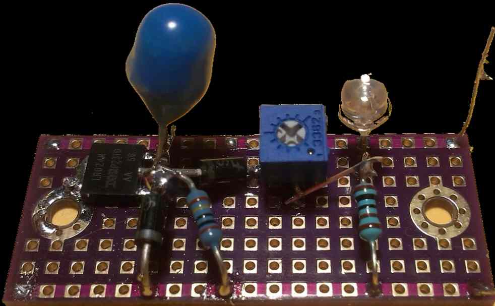
I designed this circuit in order to limit the current draw by vacuum tube heaters. When the heater is cold it has a lower resistance and the inrush current can be three to four times bigger. This is stated to be a major cause of tubes failure.The idea is simple, an n-channel mosfet is used as variable resistor. The C1 capacitor is slowly charged through R2 resistor. So the transistor will start to turn on. There is no reason to wait until the voltage across C1 reach the gate threshold. To avoid this delay the capacitor is charged very fast just below the threshold voltage. This voltage is set by R3. A fixed 2.6V reference is created with a blue led, D1. This is more than enough since the transistor is a logic level mosfet that turns on at around 2v
If the input voltage is turned off then C1 will remain charged so the limiting function will be lost for a while. This is the reason why D3 was added, to create a discharge path through the load.
Another thing I noticed is that an aluminum electrolytic capacitor will not work for C1. The leakage current is large enough to prevent it to fully charge. Because R2 is also very large, since I want to have a few seconds of limiting action. So C1 is a tantalum capacitor.
Sometimes it might be desirable to put the mosfet across the positive rail, in this case it should be a p-channel type.
Bellow there are two examples of a 500mA heater from a 6AC7 with and without current limiter. Notice the large initial current spike in the second picture:
A more precise current limiting could be obtained with a LM317 and a single resistor, but it will add a voltage drop. The circuit above has the advantage that after the initial limiting phase it cause only a very small loss of voltage thanks to the low Rds of the mosfet. Not to mention that this low Rds can be made even lower by adding in parallel as may transistors you like :).Extra gate capacity is not an issue here.
Also it should be considered the voltage threshold dependance on temperature in case significant power is disipated during current limiting.