Vacuum tube regenerative radio
This is a 5 tube regenerative receiver for 14MHz band. Building it
filled many nights and I would like to share this nice experience.
Circuit description
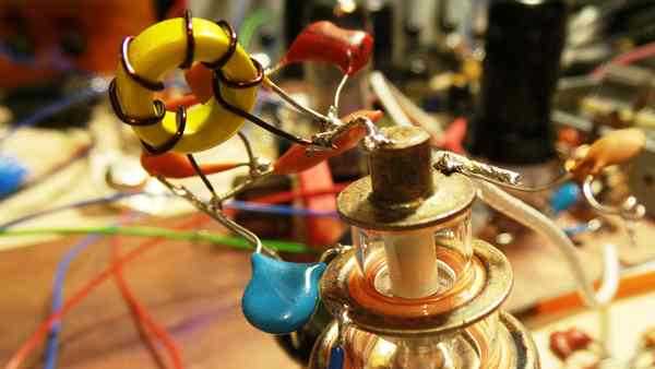
As you can see the RF amplifier use a grounded grid triode. Even if this configuration doesn’t produce maximum gain it is stable and isolates the detector from antenna. I tried many tubes. For example 12SF5 produced less than unity gain, 6C5 yield a gain of 2 and 6S9D around 7-8. So finally I have a good reason to use a “lighthouse” tube. The resonant circuit from anode is tuned to the middle of the band. At both band edges the gain decrease to about 70%. I considered that it doesn’t worth to have a variable capacitor here. The coil uses a T50-6 core. In the cathode there is another coil (L1) that increases the input impedance of the amplifier. Removing it will cause a slightly decrease of gain. By the way, the gain is controlled by C1. The antenna is a mono-band fish-pole. For 20m band, of course.
The detector stage uses a 6J4 tube (6AC7). The L3 coil has a T68-7 core. Material 7 has a better thermal coefficient than material 6 used in previous stage. The wire has a 1.2mm diameter. Because is so thick it add mechanical stability and increase Q-factor. It is also un-isolated. So is easy to move the taping point. Resistors R6 and R8 should be adjusted only once, to set the limits of regeneration control. The idea is to limit the voltage variation obtain with R7 to the minimum required value to have a smooth control. The detector is supplied from a 150V gas discharge regulator tube. The C5 and C6 are series/parallel combinations of silver-mica capacitors in order to obtained desired value. The easiest way to set the band limit covered by detector is to use a signal generator. The coil tap is at one wound from the cold end.
The audio preamplifier is built with a 6J8(6SJ7) tube. This is a purpose build low noise audio amplifier tube. Its main feature is good shielding between heater and cathode. For example 6J4(6AC7) is not well suited for audio applications with heater supplied with AC voltage. The C17 capacitor limits the high frequency gain of the stage. And there are plenty of sharp noises on a regenerative receiver. Audio amplifier uses a 6P9 (6AG7) tube. This high gain pentode need a 10k load according to specs. I found this to be very tolerant actually. First I use a 60VA toroid transformer. For primary I used the 230V winding and for secondary winding I just made 4-5 wounds. It sound very well, the same like when I replace it with a special output transformer.

Circuit description
As you can see the RF amplifier use a grounded grid triode. Even if this configuration doesn’t produce maximum gain it is stable and isolates the detector from antenna. I tried many tubes. For example 12SF5 produced less than unity gain, 6C5 yield a gain of 2 and 6S9D around 7-8. So finally I have a good reason to use a “lighthouse” tube. The resonant circuit from anode is tuned to the middle of the band. At both band edges the gain decrease to about 70%. I considered that it doesn’t worth to have a variable capacitor here. The coil uses a T50-6 core. In the cathode there is another coil (L1) that increases the input impedance of the amplifier. Removing it will cause a slightly decrease of gain. By the way, the gain is controlled by C1. The antenna is a mono-band fish-pole. For 20m band, of course.
The detector stage uses a 6J4 tube (6AC7). The L3 coil has a T68-7 core. Material 7 has a better thermal coefficient than material 6 used in previous stage. The wire has a 1.2mm diameter. Because is so thick it add mechanical stability and increase Q-factor. It is also un-isolated. So is easy to move the taping point. Resistors R6 and R8 should be adjusted only once, to set the limits of regeneration control. The idea is to limit the voltage variation obtain with R7 to the minimum required value to have a smooth control. The detector is supplied from a 150V gas discharge regulator tube. The C5 and C6 are series/parallel combinations of silver-mica capacitors in order to obtained desired value. The easiest way to set the band limit covered by detector is to use a signal generator. The coil tap is at one wound from the cold end.
The audio preamplifier is built with a 6J8(6SJ7) tube. This is a purpose build low noise audio amplifier tube. Its main feature is good shielding between heater and cathode. For example 6J4(6AC7) is not well suited for audio applications with heater supplied with AC voltage. The C17 capacitor limits the high frequency gain of the stage. And there are plenty of sharp noises on a regenerative receiver. Audio amplifier uses a 6P9 (6AG7) tube. This high gain pentode need a 10k load according to specs. I found this to be very tolerant actually. First I use a 60VA toroid transformer. For primary I used the 230V winding and for secondary winding I just made 4-5 wounds. It sound very well, the same like when I replace it with a special output transformer.
Results:
Bellow you can see a movie with the working receiver. As you can see it is pretty sensitive, however selectivity is definitely not its strong point. But consider that whole selectivity is obtained with a single LC circuit. Tuning require skill. Actually the movie was made before I figure out that the regeneration level has to be increased to make the voice more clear. The regeneration control change also a little the frequency so you might be tempted to adjust the pitch in this way, but this is wrong. Also the antenna capacitor should be set to minimum value required to listen to desired signal in order to minimize strong signals interference. Overall I was very pleased with the performance of such a simple radio. Of course, many improvements can be made but the added complexity will make the radio comparable with a super-heterodyne design witch is in another class of performance.
Bellow you can see a movie with the working receiver. As you can see it is pretty sensitive, however selectivity is definitely not its strong point. But consider that whole selectivity is obtained with a single LC circuit. Tuning require skill. Actually the movie was made before I figure out that the regeneration level has to be increased to make the voice more clear. The regeneration control change also a little the frequency so you might be tempted to adjust the pitch in this way, but this is wrong. Also the antenna capacitor should be set to minimum value required to listen to desired signal in order to minimize strong signals interference. Overall I was very pleased with the performance of such a simple radio. Of course, many improvements can be made but the added complexity will make the radio comparable with a super-heterodyne design witch is in another class of performance.
Component list:
C1:50pF C2:10nF C3:10uF C4:10nF C5:312pF C6:54pF
C7:3-18pF C8:82pF C9:150nF C10:120pF C11:150nF C12:8.2pF
C13:600pF C14:10nF C15:1nF C16:47uF C17:10nF C18:10uF
C19:100uF C20:150nF C21:100uF C22:100uF C23:4.7nF
R1:400 R2:3k3 R3:1k R4:13k R5:100k R6:220k
R7:10k R8:220k R9:4M R10:390k R11:1k R12:57k
R13:330k R14:100 R15:10k
D1: zenner 100V
D2: zenner 150V
L1: 30 wounds on ferrite core (diameter 18mm)
L2: 7 wounds T50-6
L3: 8 wounds T68-7