TDA7000 - A Complete FM Radio on a Chip
Page 9 of 11
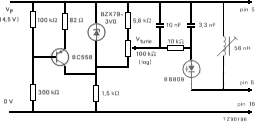
Circuit with variable-capacitance diode tuning Since it is only necessary to tune the local-oscillator coil, it is very simple to modify the circuit of Fig.1 for variable- capacitance diode tuning. The modifications are shown in
Fig.14. A circuit board layout for the modified receiver and a photograph of a complete laboratory model are shown in .Fig. 15
 TDA 7000 ( Fig. 1)
Fig.14 Variable-capacitance diode tuning for the local-oscillator. Additonal measures must be taken to ensure temperature stability
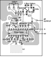
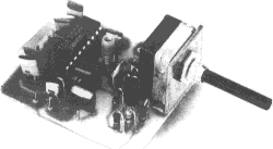
Fig.15 Circutt board layout and complete model of a TDA7000 radio with varlable-capacitance diode tuning. This is the same pcb as shown in Fig.1 2
The TDA7000 can also Pe used for reception
of narrow- band fm. signals. In this case, the local-osciflator is crystal-
controfled as shown in Fig.16 and there is therefore hardly any compression
of the i.f. swing by the FLL. The devia- tion of the transmitted carrier
frequency due to modula- tion must therefore belmited to prevent severe
distortion of , the demodulated audio signal.
The component values in Fig.16 result in an i.f. of 4.5 kHz and an if.
bandwidth of 5 kHz (Fig. 17). If the i.f.
is multiplied by N, the values of capacitors
C l -L and C18 in the all-pass filters and the values of filter capacitors
C7, C8, C 10, C l 1, and C 12 must be multiplied by l /N. For improved
i.f. selectivity to achieve greater adjacent channel attenuation, second-order
networks can be used in place of Clo and Cl 1.
In this circuit the detuning noise generator is not used. Since the circuit
is mainly for reception of audio signals, the audio output must be passed
through a low-pass Chebyshev filter to suppress i.f. harmonics.