TDA7000 - A Complete FM Radio on a Chip
Page 3 of 11

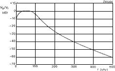
Fig.3 Measured response of the i,f, filter
F.M. demodulator
The quadrature f.m. demodulator M2 converts the i.f. variations due to
modulation into an audio frequency voltage. It has a conversion gain of
-3.6 V/MHz and requires phase quadrature inputs from the i.f. limiter/amplifier.
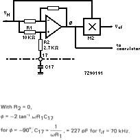
As shown in Fig.4, the 90* phase shift is provided by an active all-pass
filter which has about unity gain at all frequencies but can provide a
variable phase shift, dependent on the value of external capacitor C 17.

To improve the performance of the all-pass filter with the amplitude limited i.f. wave-form, R2 has been added. Since this influences the phase angle, the value of C17 must be incressed by 45% i.e. to 330 pF for fif - 70 kHz. |
Fig,4 F.M. demodulator phase shift circuit all pass filter)
I.F. swing compression with the FLL
With a nominal Lf. as low as 70kHz, severe harmonic distortion of the audio
output would occur with an i.f. deviation of ±75 kHz due to full modulation
of a received f.m. broadcast signal. The FLL of the TDA7000 is therefore
used to compress the i.f. swing by using the audio output from the f.m.
demodulator to shift the local-oscillator frequency in opposition to the
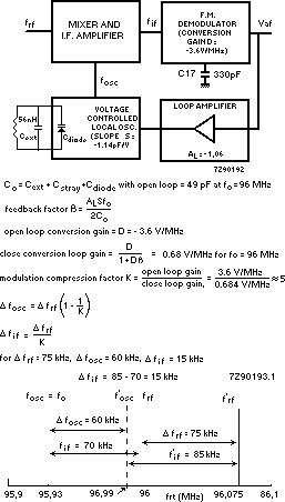
i.f. deviation. The principle is illustrated in Fig.5, which shows that
an i.f. deviation of 75 kHz is compressed to about 15 kHz. The THD is thus
limited to 0.7% with ±22.5 kHz modulation, and to 2.3% with ±75 kHz modulation.

Flg.5 I.F. swing compression with the FLL