TDA7000 - A Complete FM Radio on a Chip
Page 2 of 11
path, Only the local-oscillator needs to be tuned, so tracking
and distortion problems are eliminated.
As shown in Fig.1, the TDA7000 consists of a local-oscillator
and a mixer, a two-stage active if. Filter followed by an if. limiter/amplifier,
a quadrature fm. demodulator, and an audio muting circuit controlled by
an i.f. waveform correlator. The conversion gain of the mixer, together
with the high gain of the i.f. limiter/amplifier, provides a.v.c. action
and effective suppression of a.m. signals. The r.f. input to the TDA7000
for -3 dB limiting is 1.5 µV. In a conventional portable radio,
limiting at such a low r.f. input level would cause instability because
higher harmonics of the clipped i.f. signal would be radiated to the aerial.
With the low i.f. used with the TDA7000, the radiation is negligible.
Active Lf. filter
The first section of the i.f. filter (AFIA) is a second-order
low-pass Sallen-Key circuit with its cut-off frequency determined by internal
2.2 kOhm resistors and external capacitors C7 and C8. The second section
(AFIB) consists of a first-order bandpass filter with the lower limit
of the passband determined by an internal 4.7 kOhm resistor and external
capacitor C11. The upper limit of the passband is determined by an internal
4.7 kOhm resistor and external
The TDA7000 is available in either an 18-lead plastic DIL package (TDA7000),
or in a 16-pin SO package(TDA7010T). Future developments will include reducing
the present supply voltage (4.5 V typ.), and the introduction of fm. stereo
and a.m./f.m. versions.
CIRCUIT DESCRIPTION
BRIEF DATA

typical supply voltage	VP	4.5 V
typical supply current	lp	8mA
r.f. input frequency range	frf 1.5 to l IOMHZ
sensitivity for -3 dB limiting e.m.f.
with Zs = 75f2, mute disabled	Vrf-3 dB	l-5AV
maximum signal input for
THD < 1001o, Af = ±75 kHz
e.m.f. with Zs = 75 92	Vrf	200mV
audio output (T.M.S.) with
RL = 22 U2, Af = ±22.5 kHz	VO	75 mV
To prevent distortion with the low i.f. used with the TDA7000, it is necessary
to restrict the if. deviation due to heavily modulated r.f. signals to
± l 5 kHz. This is achieved with a frequency-locked loop (FLL) in which
the output from the fm. demodulator shifts the local-oscillator frequency
in inverse proportion to the if. deviation due to modulation.
capacitor C10. The final section of the i.f. flIter consists
of a first-order low-pass network comprising an internal 12 kOhm resistor
and external capacitor C12. The overall i.f. filter therefore consists of
a fourth-order low-pass section and a first-order high-pass section. Design
equations for the filter are given in Fig.2. Figure 3 shows the measured
response for the filter.
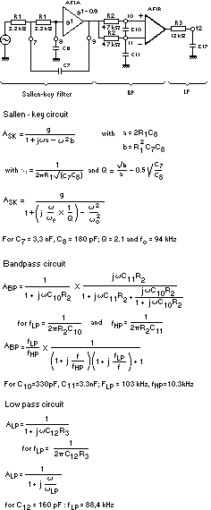
Fig.2 I.F. filter of the TDA7000