Transverter 70MHz (4m) to 28MHz (10m) |
Under Construction
While researching 70 MHz to 28 MHz transverter designs, I examined several well-known approaches, including the Anglian by G4DDK, Cray by G4FRE/WG3I (VHF-UHF DX Book - 1st Edition, page 9-20), the popular OZ2M project based on the 6 m transverter by OE9PMJ, and the TR70H by DB6NT.
After evaluating these designs, I chose the Anglian transverter as the basis for my project, incorporating several modifications of my own:
- Integrated PLL with an OCXO reference and a simplified Butler local oscillator
- RF VOX transmit/receive switching
- Redesigned IF switching circuit using a relay
- A different IF diplexer
- An IF notch filter to suppress local oscillator leakage
In addition, I carried out a number of experiments aimed at optimizing receiver and transmitter intermodulation performance.
Measured Performance (70.000–70.300 MHz):
Receiver
- Noise Figure (NF): 2.5 dB
- Input Third-Order Intercept (IIP3): > +2 dBm ( 2 x -22dBm input tones, 0.1MHz spacing )
- Conversion Gain: 26 dB
- Image Rejection (14 MHz): > 70 dB
- 42MHz LO Leakage to IF: -65 dBm
Transmitter
- Saturated output power: 21.5 dBm
- IMD3: -50 dBc at 17 dBm PEP
- Spurious emissions: -70 dBc at 20 dBm output
- Harmonics vs output power: 2nd harmonic -54 dBc and 3rd harmonic -43 dBc @ 20dBm; 2nd harmonic -68 dBc and 3rd harmonic -68 dBc @17dBm
Frequency stability: better than 1 Hz
Current consumption at 6V: cold startup 0.7A; after the OCXO has warmed up RX 0.4A , TX 0.51A
The initial receiver conversion gain exceeded 30 dB, significantly higher than the 24 dB specified for the original Anglian design. The excessive gain can degrade the receiver's large-signal performance. To improve linearity, I introduced an additional 6 dB attenuator ahead of the mixer. This modification resulted in a noticeable improvement in IIP3, while the noise figure increased only slightly from 1.7 dB to 2.5 dB. Even so, this value remains more than adequate, as it is well below the natural noise floor of the 4 m band. It is worth noting that the PSA4-5043 MMICs are indeed high-performing.
I also performed several experiments to reduce the gain of the PGA-105+ post-mixer amplifier from 16 dB to approximately 10 dB by various RC feedback networks. Although the gain reduction was successful, the amplifier's intermodulation performance deteriorated, making this approach less attractive. Eliminating this gain stage altogether would further improve the overall transverter IIP3, but at the expense of reduced conversion gain. One idea worth investigating is the use of a Norton amplifier with a gain of less than 10 dB and high IP3. I evaluated several MMICs for this stage, and the PGA-105+ offered a good overall compromise between gain and linearity.
The final receiver gain of 26 dB proved to be the optimum compromise for my application. It has enough gain for my homebrew 10 m HF transceiver, whose receiver front end does not include a built-in preamplifier.
The prototype version also included a 12 V to 6.5V switching preregulator based on the LTC3621 (1 MHz), placed ahead of the on-board 5V LDO regulator. After extensive testing, I decided to remove it because of the additional noise it introduced into the receiver signal path, despite shielding of the sensitive circuit section. Using a switching regulator on the same PCB as a highly sensitive receiver chain is generally discouraged.
The recommended supply voltage for the transverter is 6V, this minimizes the power dissipated by the on-board 5V LDO regulator.
A 13 MHz OCXO was selected as the PLL reference instead of the more common 10 MHz option to ensure that none of its harmonics fall within the 70 MHz band, thereby avoiding receiver self-quieting. However, both options are supported, with the PLL configuration selection being made via a 10/13 MHz jumper.
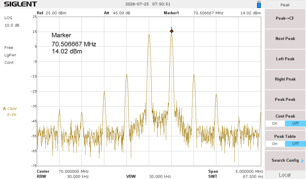
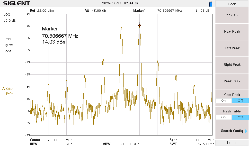
On the transmit (TX) path, I recommend keeping the IF level at the input of the ADE-1H mixer below -3 dBm to achieve excellent intermodulation distortion (IMD) performance. For the output stage, the WJ AH1 MMIC has proven to be the best choice. Its newer equivalent, the Mini-Circuits PHA-1+ MMIC, performs slightly worse, with slightly higher IMD products at the same output power.

 Schematic Transverter 70MHz / 28MHz vers.1.1
PCB Transverter 70MHz / 28MHz vers.1.1
Firmware Attiny25 - 42MHz PLL, reference 10 / 13MHz (default fuse bits)
WJ AH1 MMIC output IMD @ 20dBm PEP
PHA-1+ MMIC output IMD @ 20dBm PEP