KENWOOD TK-880 |
![]()
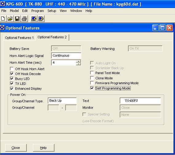
![]() PC Software programming for TK-880: >>KPG-60D<<
PC Software programming for TK-880: >>KPG-60D<<
Update 2019: >>KPG-62D version 2.00<< tested by YO8RLK with TK880-1 and USB/UART interface.
![]() Serial cable between PC and Radio: >>Programming Interface KPG-46 Schematic<<
Serial cable between PC and Radio: >>Programming Interface KPG-46 Schematic<<
![]() TK-880 >>Service Manual rev. E<<
TK-880 >>Service Manual rev. E<<
1. Channels programming procedure can be performed by PC software or using Front Panel keys.
- Connect data cable and go to KPG-60D PC software at Edit / Channel Information.
Radio display when internal CPU is accessed by computer:

- Front panel programming is possible only if "Self Programming Mode" option was previously selected by PC software (go to Edit / Option Feature and then upload to radio).
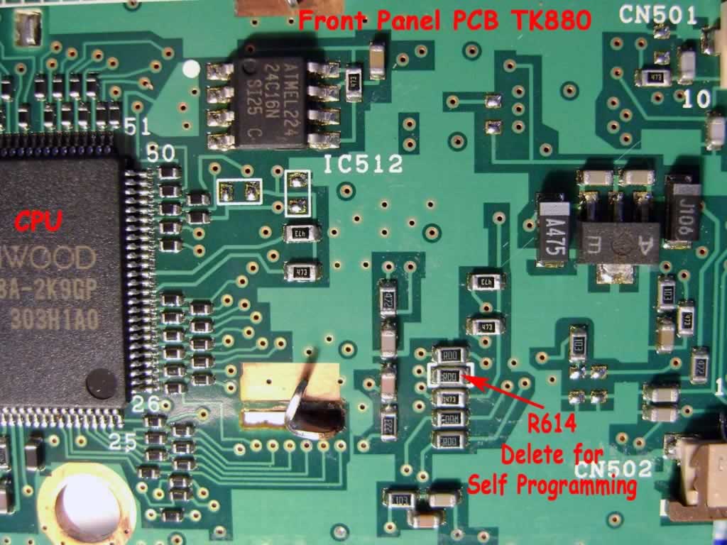
In order to activate the feature, R614 "zero ohm" resistor must to be deleted! This resistor is located on front panel PCB, near to CPU.
After that, the radio channels can be programmed directly by front panel keys.
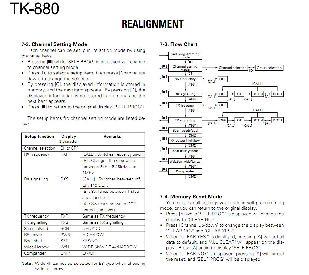
Keep pressed {CALL} key, in same time switch ON the radio. "SELF PROGRAMMING" option can be accessed. Use realignament guide to see key functions (SM page 18).

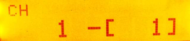
Other pics during front panel programming:
Group 1 - Channel 1
RX Frequency (PMR CH-1)

Next steps can be easily understood...
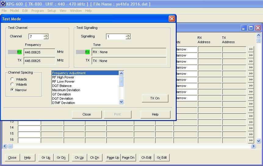
2. Realignament / tuning of radio can be done by PC software or using Front Panel keys
Frequency accuracy, modulation deviation, TX power, RX sensitivity and other options are available.
- Open KPD-60D, TEST Menu is easy to use. Connect data cable and go to Program / Test Mode.
- Realignament using Front Panel keys is possible only if "Panel Test Mode" option was previously selected by PC software (go to Edit / Option Feature and then upload to radio).
Keep pressed {B} key, in same time switch ON the radio. "UHF F1" screen appear for short time, after that "Test Mode" can be accessed.
Check the service manual for more details at Adjustment - page 45.

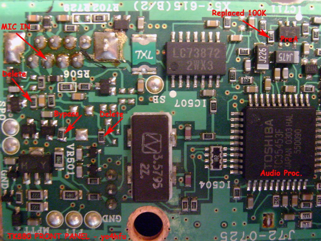
Poor signal / noise ratio of TX modulation - modification
During testing I noticed a low signal to noise ratio for TX. Background noise was higher than my GP300 monitor. After investigation, IC711 microphone preamplifier was found with poor perfomances. IC preamplifier is located on Front Panel PCB.
I tried to apply 1nF roll off capacitor in the feedback loop. The noise was decreased enough, but also high spectrum of audio modulation was affected.
Next try was to decrease the gain. Feedback R721(330K) resistors was replaced by 100K. Good results but level of modulation was affected. Immediately i saw some resistors between microphone connector and preamplifier stage. Why to decrease the microphone level using resistors and after again to boost the signal? The S/N ratio will be forever degraded...
All dividers were removed in order to increase the original level of modulation: R512(680) removed; R724(4K7) bypassed; R725(15K) removed (resistors values found in my radio, not same with Service Manual. Please check SM diagram).
Final result: improved TX modulation, close to Motorola quality...hi.
73!