FM Modulation Analyzer 531 (clone) |

During experiments with stereo coders, I ran into the challenge of monitoring and analyze the MPX signal. After studying various technical documents, I decided to partially replicate the Inovonics 531 FM Modulation Analyzer, as its documentation is detailed enough and schematics are included. Inovonics 531N is same equipment but the controller section is updated for remote network connection.
I first tested the stereo decoder block and the stereo audio path. The performance turned out to be excellent (especially compared to various stereo decoder ICs), so I continued with the RF section, the controller, and front / rear panels. What started as simple curiosity quickly turned into the ambition to complete this project, which required many hours of work designing PCBs, writing firmware, and even manually winding IF transformers.
I tried to follow the original schematic as closely as possible, but had to adapt the RF block to the components I had available and build the controller around an Atmega2560. I also noticed a few errors in the original schematic, which I corrected and made available below.
I want to emphasize that this is not a simple project — it requires precision components, proper calibration instruments, and solid knowledge. The final result behaves very similarly to the original product and is extremely useful in the laboratory of anyone passionate about transmitters and stereo coders.
I did not have access to an original Inovonics 531 unit, just inspired by photos, videos, and the manual available online.
The information on this page is **strictly non-commercial** and intended only for personal use!
![]() Other notes:
Other notes:
- Y3 crystal: replaced from 6.4 MHz to 2.0 MHz, to avoid internal self-quieting.
- IC61 (PLL): PFD is set to 10 kHz by registers, even though the available frequency step is 100 kHz; otherwise, the PLL lock-detection circuit Q17/Q18 does not operate correctly.
- R210: bypassed in order to achieve the best stereo separation via R211. IC46 (4053) tested from both Texas Instruments and NXP; the NXP version gives slightly better stereo separation.
- All CMOS ICs are from Texas Instruments CD40xx, as they are specified for 20V power supply. The NXP HEF40xx versions seem specified for a maximum of 18V, and likely work as well.
Inovonics 531 internal power supply is +/-9V.
- IC62 OP279 replaced by OPA2237 or other rail-rail operational amplifier. Warning: an unsuitable operational amplifier will not be able to correctly track the tuning voltage across the entire range.
- R113/R88 switching not used (ADC range function according Inovonics 531N documentation). Both are always "grounded" via CPU (or rather, the MCU).
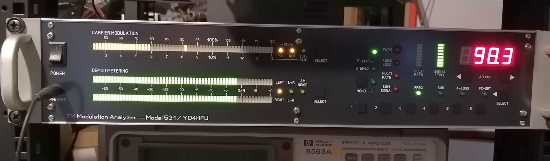
- One more MAX7219 was added on front panel board in order to extend the bargraphs with few more LEDs.
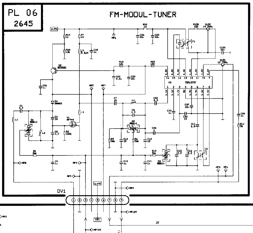
- TUN1 (FM Tuner Module; Inovonics P/N 1266) replaced with Blaupunkt frontend TDA1575 from a Blaupunkt SC202(C) car radio cassette. MMIC LO amplifier was added between frontend and IC61 PLL input.
Both 10.7 MHz ceramic filters have been removed. The IF output is now taken from the R150 pad on the F1 coil (before Q150 filter).
- R115 resistor removed to avoid voltage clamping at 3.125V. In this way entire range ADC 0-5V can be used.
![]()
![]() Inovonics 531 web page
Inovonics 531 web page
![]() Inovonics 531 manual (link)
Inovonics 531 manual (link)
![]()
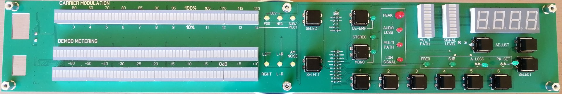
![]() Front Panel v1.1 (gerber) - as mask
Front Panel v1.1 (gerber) - as mask
![]() View Front Panel
View Front Panel
![]() Front Board v1.1 (gerber)
Front Board v1.1 (gerber)
![]() View Front Board
View Front Board
![]() Rear Panel v1.0 (gerber) - as mask
Rear Panel v1.0 (gerber) - as mask
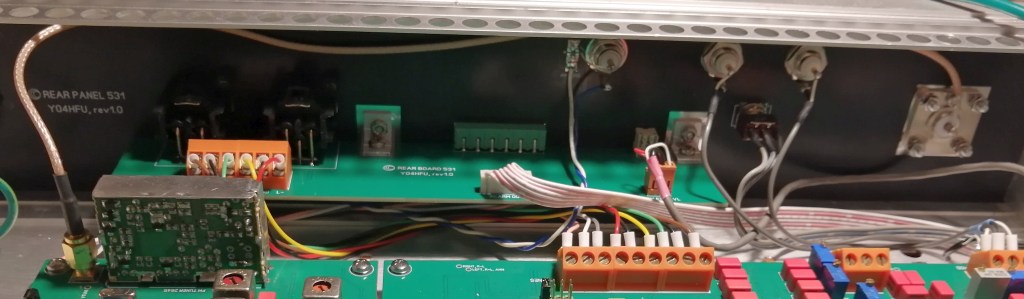
![]() View Rear Panel
View Rear Panel
![]() Rear Board v1.1 (gerber)
Rear Board v1.1 (gerber)
![]() View Rear Board
View Rear Board
![]() Main board v1.1 (gerber)
Main board v1.1 (gerber)
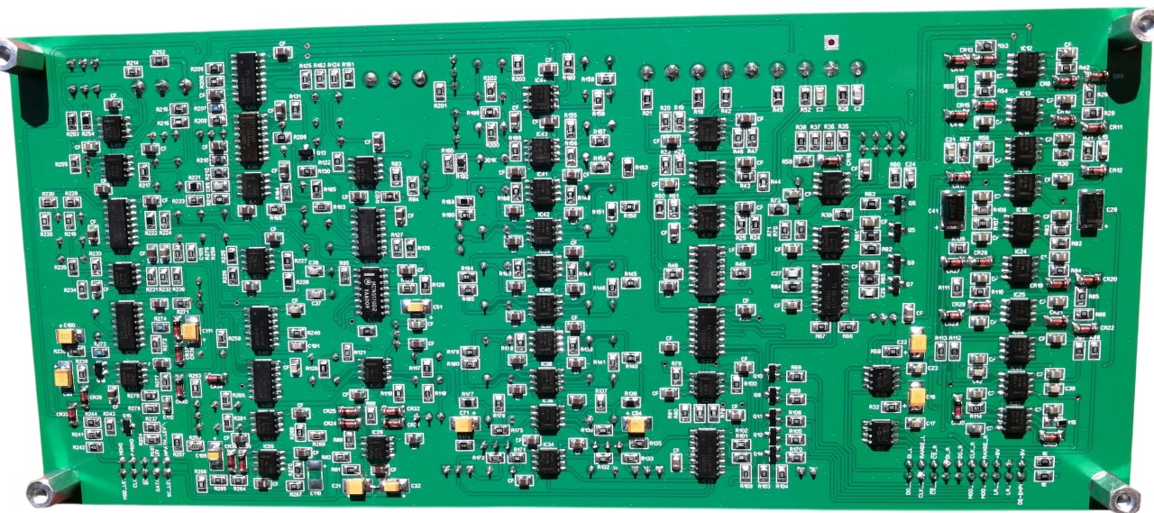
![]() View Main Board >>TOP<< and >>BOTTOM<<
View Main Board >>TOP<< and >>BOTTOM<<
![]() RF board v1.1 (gerber)
RF board v1.1 (gerber)
![]() View RF Board >>TOP<< and >>BOTTOM<<
View RF Board >>TOP<< and >>BOTTOM<<
![]() CPU board v1.1 (gerber)
CPU board v1.1 (gerber)
![]() CPU schematic ATmega2560
CPU schematic ATmega2560
![]() View CPU Board >>TOP<< and >>BOTTOM<<
View CPU Board >>TOP<< and >>BOTTOM<<
![]()
![]() Firmware ATmega2560 v1.2
Firmware ATmega2560 v1.2
![]() Fuse Bits
Fuse Bits
![]()
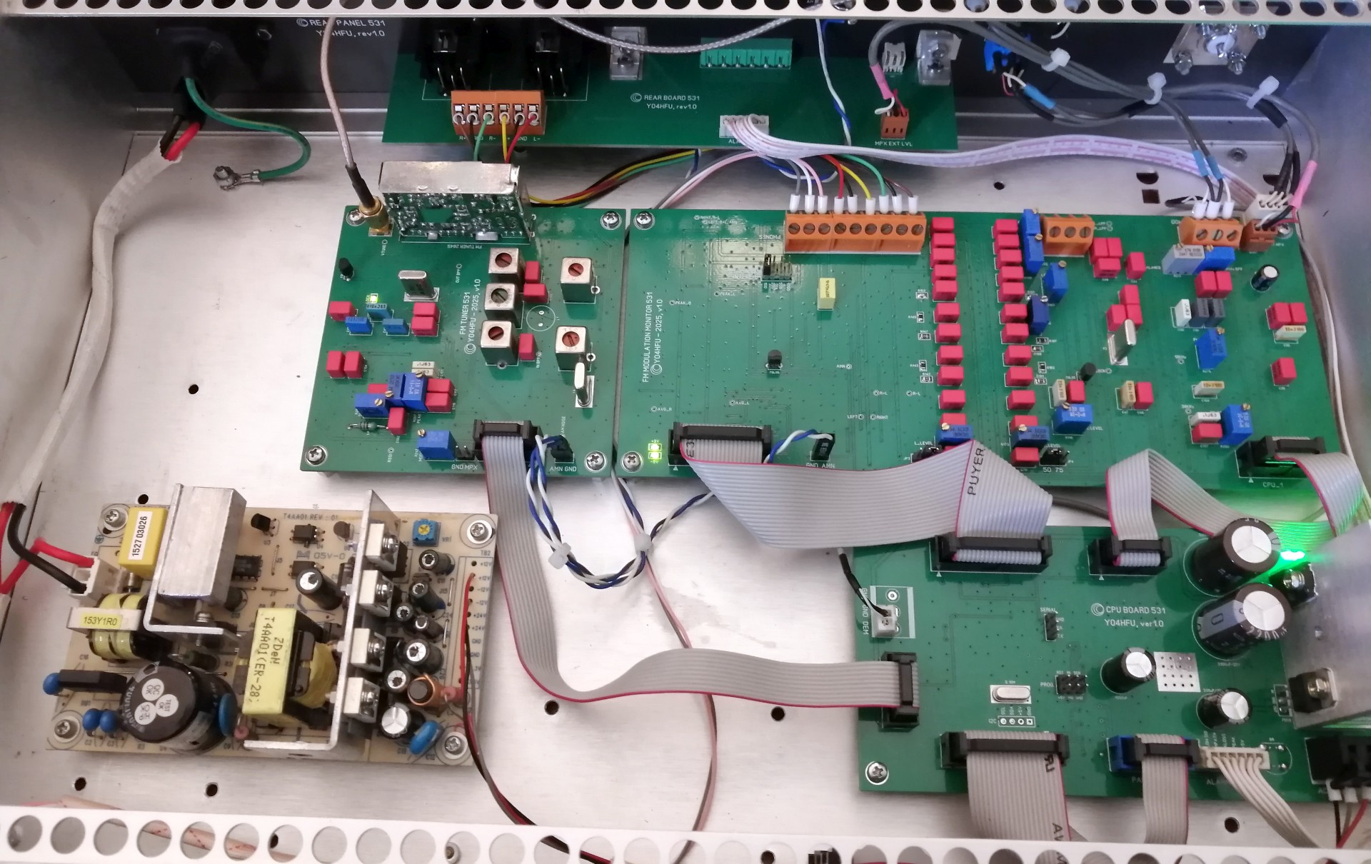
![]() Internal View - 531 Clone
Internal View - 531 Clone
![]() BOM Panel
BOM Panel
![]() RF Frontend module schematic
RF Frontend module schematic
![]() IF transformers and coil details
IF transformers and coil details
![]() 531 schematic mods
531 schematic mods