Eshail QO-100 transverter |
Es’hail-2 carries two amateur radio transponders operating in the 2400 MHz and 10450 MHz bands. A 250 kHz bandwidth linear transponder intended for conventional analogue operations and an 8 MHz bandwidth transponder for experimental digital modulation and DVB amateur television.
Narrowband transponder requirements:
Uplink: 2400.050 - 2400.300 MHz, RHCP polarization
Downlink: 10489.550 - 10489.800 MHz; linear vertical polarization
Various solutions can be used to access the satellite using TV LNBs, SDR, dedicated transverter, home made up/down converters, etc.
Equipment requirements:
- home made 100% if is possible
- small price using old parts from mobile phones and GSM/CDMA equipment
- good stability of frequency
- no frequency drift between Tx/Rx
- easy reading of actual frequency
- outdoor unit to avoid expensive coaxial for 2,4GHz transmitter
- no power supply or control cables between outdoor unit and shack. Only one cheap coaxial feeder.
- no mandatory computer to make a QSO. Optional SDR waterfall only for band monitoring
- the main transceiver to be FT847 432MHz
- enough uplink power/antenna gain
- RF VOX switching
Entire up/down converter is drive by LMX2330 dual PLL. Again I use Attiny 25/45/85 uC in order to send registers configuration over "3 serial wire" protocol. LO frequency can be changed for IF 434.5MHz or 145.5MHz by uC jumper (read about image rejection). 434MHz version is selected when jumper is OPEN.
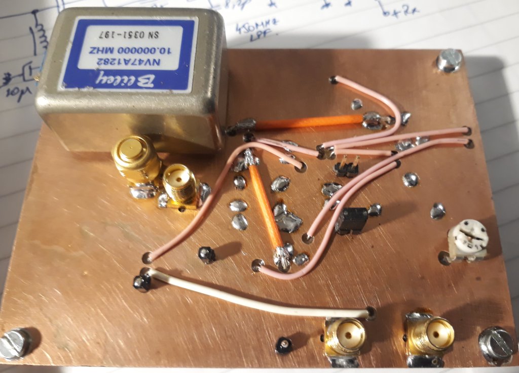
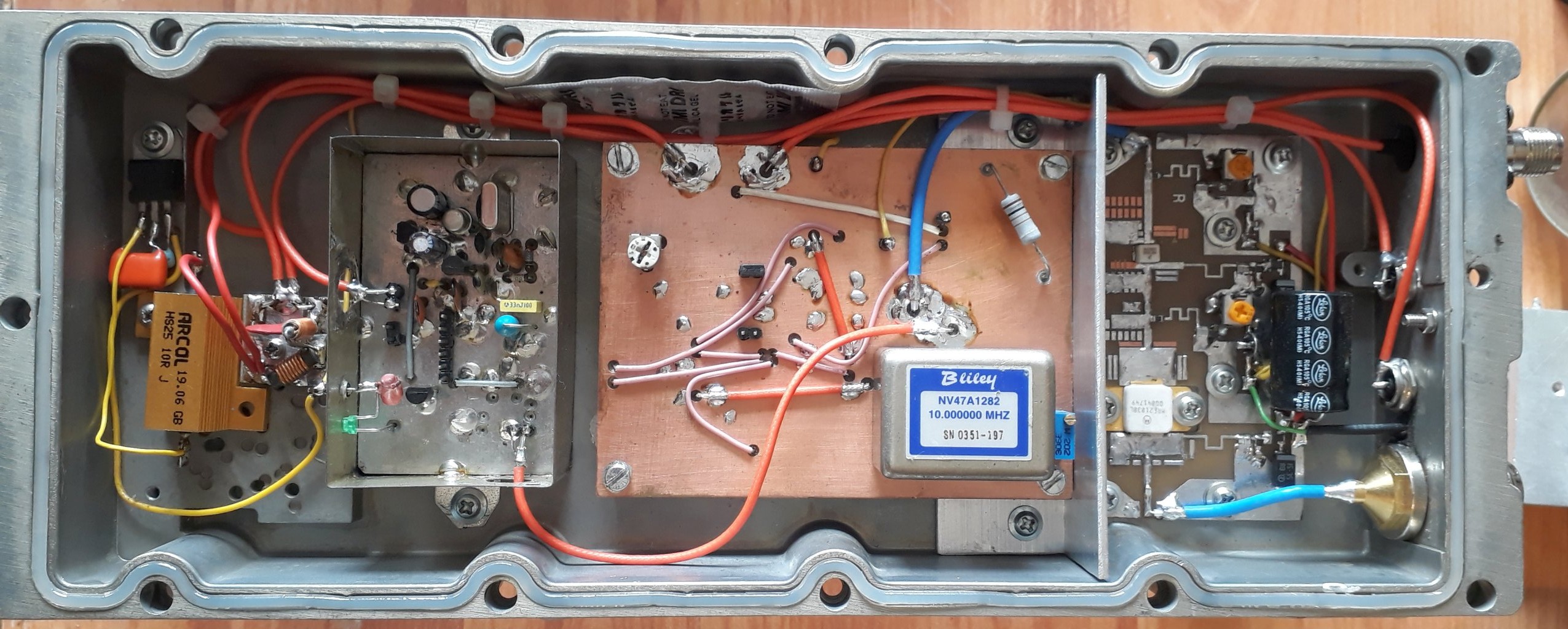
Reference oscillator is an 10MHz OCXO (Bliley NV47). Frequency stability is excellent after >5 minutes from power up. GPS disciplined oscillator is not necessary. Same 10MHz signal is used by 27MHz LNB PLL. In this way frequency drift between Rx/Tx is Zero.
PLL tuning voltage keeps steady two independents VCOs. I can't recommend any specific VCO type because i use some old parts modified for center frequency around of 1965.5MHz Tx and 305MHz Rx. VCOs can be replaced by simple Collpits oscillator tuned with varicap diode. For IF 145MHz version, center frequency of VCOs are 2254.5MHz Tx and 594MHz Rx.
Downlink 739.5/434.5MHz converter
LNB IF signal is converter to 70cm band by double balanced mixer. 12V LNB power supply is sent via coaxial cable. No additional gain is required because LNB gain is more than enough.
UPLINK 434.5/2400MHz converter
434MHz signal (max. 5W) is attenuated and then converted by double balanced mixer. Output 2400MHz is filtered by two pieces Murata SF2124E SAW filters and boosted up to +21dBm (125mW). Image frequency has good rejection but for 145MHz IF version more filtering is required. Better to use IF 434MHz version.
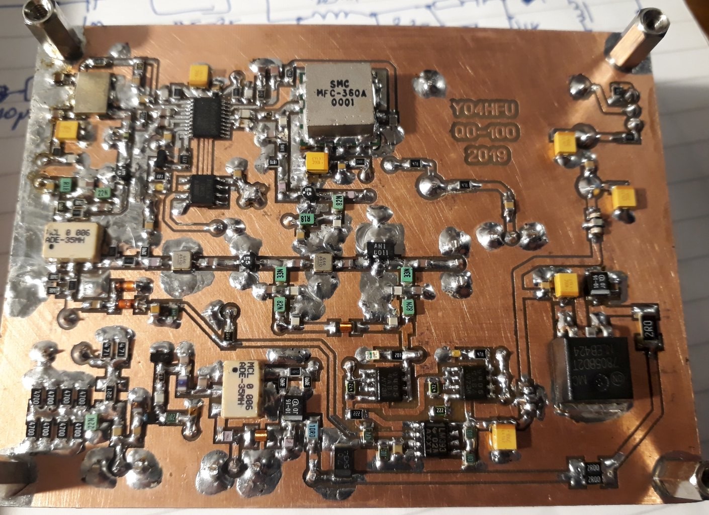
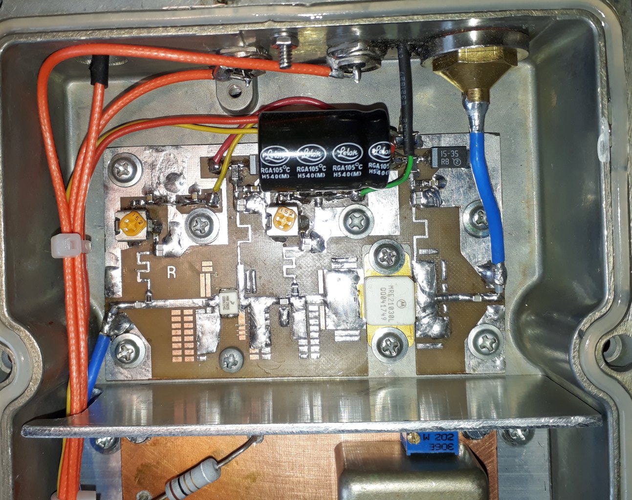
2,4GHz power amplifier was designed by ADS software. MRF282S and MRF21030 were selected due to low price. Output power is about 10W. Fine adjustments of matching microstrip lines are required. PCB material is cheap 0,8mm double side FR4. Please note approximate electrical length / impendance of microstrip lines.
ADE-35MH mixer is level +13dBm but also +7dBm mixer can be installed. LO level will be decreased by higher value of attenuator pads.
![]()
![]() Eshail transverter schematic rev1.2
Eshail transverter schematic rev1.2
![]() 2,4GHz Power Amplifier schematic
2,4GHz Power Amplifier schematic
![]() Power amplifier PCB (opposite side is ground plane)
Power amplifier PCB (opposite side is ground plane)
![]() Photo of uplink/dowlink converter board TOP and BOTTOM side
Photo of uplink/dowlink converter board TOP and BOTTOM side
![]() Photo of MRF21030 power amplifier
Photo of MRF21030 power amplifier
![]() Photo of QO-100 Transverter, during testing
Photo of QO-100 Transverter, during testing
![]() Attiny25/45/85 firmware
Attiny25/45/85 firmware
![]() Attiny Arduino Sketch free to modify
Attiny Arduino Sketch free to modify