SUN/MOON DIGITAL NOISE METER |
Sun/Moon Digital Noise Meter designed to achieve next requirements:
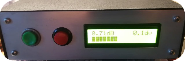
- Noise value indication and bargraph, I2C LCD 2x16.
- "Zero" calibration to Cold Sky or other reference using a push button.
- Adjustable bargraph sensitivity 0.1, 0.2, 0.5, 1dB / division. Maximum bargraph range: 15dB.
- Audio VCO [450...2200Hz] proportional with the noise indication, useful during antenna peak adjustment.
- Software "dB" calibration, screwdriver less.
- Good sensitivity to monitor microwave transverter output (144MHz).
- Cheap uC, Arduino compatibility, 10 bits ADC or better.
The PCB can also support the well know analog version of sun noise meter (never tested).
Two push buttons are used, both of them have dual function by short/long (~5 seconds) pressing:
PB1 - Zeroing and Calibration Menu
PB2 - Bargraph scale "dB/div" and On/Off audio VCO
![]() ADJUSTMENT AND CALIBRATION
ADJUSTMENT AND CALIBRATION
- Install MODE jumpers to "D" position, apply 12V power supply.
- Inject about -45dBm / 145MHz carrier and adjust bandpass filters for maximum TP2 voltage. Decrease RF signal down to -80dBm and repeat the adjustment. Secure BPF's ferrite cores.
- Press and hold PB1 until Calibration Menu appears.
- Inject -75dBm* / 145MHz then press PB1.
- Inject -60dBm / 145MHz then press PB1. Calibration completed, EEPROM values stored.
![]() *NOTE:
15dB difference between 2 points calibration, absolute level is not critical. Use 15dB pad attenuator or calibrated RF signal generator.
*NOTE:
15dB difference between 2 points calibration, absolute level is not critical. Use 15dB pad attenuator or calibrated RF signal generator.
-75dBm...-60dBm input range was chosen to match with transverter output and to avoid nonlinearity errors of logaritmic detector AD8307.
Different calibration points can be used according particular requirements, for example: -80dBm/-65dBm. Hardware/software changes are not required.
Avoid very low level due to RF chain internal noise floor and AD8307 nonlinearity. By calibration procedure, the uC "learns" the detector's log response function (Pin/Vout).
![]() ACCURACY CHECK
ACCURACY CHECK
- Inject -75dBm / 145MHz and press PB1. Noise indication will be automatically adjusted to "0.0dB".
- Inject -60dBm / 145MHz, noise indication will be 15dB.
- Inject different levels between -75dBm...-60dBm and check indication accuracy. Example: with -70dBm input, noise value will be 5dB. Small errors can be observed due to AD8307 response.
- Press and hold PB2 to enable/disable audio VCO option. Press PB2 to change dB/division scale of bargraph. Tone frequency will be shifted according bargraph indication.
![]() HOW TO USE
HOW TO USE
- Connect Noise Meter to microwave transverter (144MHz output).
- Point dish antenna to the most quiet "COLD SKY" point and then press PB1 "ZERO".
- Point dish antenna to SUN and read noise value difference.
- Adjust focal position of horn for best noise value. Higher noise difference between SUN / COLD SKY means better performance of RX chain.
![]() NOTE: Recommended power supply voltage: 12Vdc. For higher input voltage, use an additional 12V voltage regulator, otherwise MMICs damage can occur.
NOTE: Recommended power supply voltage: 12Vdc. For higher input voltage, use an additional 12V voltage regulator, otherwise MMICs damage can occur.
Negative noise readings can occur when actual measured noise level is smaller than stored zero reference. New zeroing is required on minimum noise, the most quiet Cold Sky point.
![]()
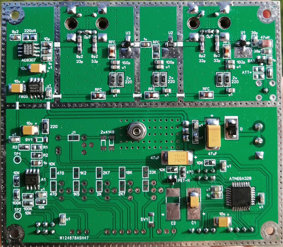
![]() PCB Top View
PCB Top View
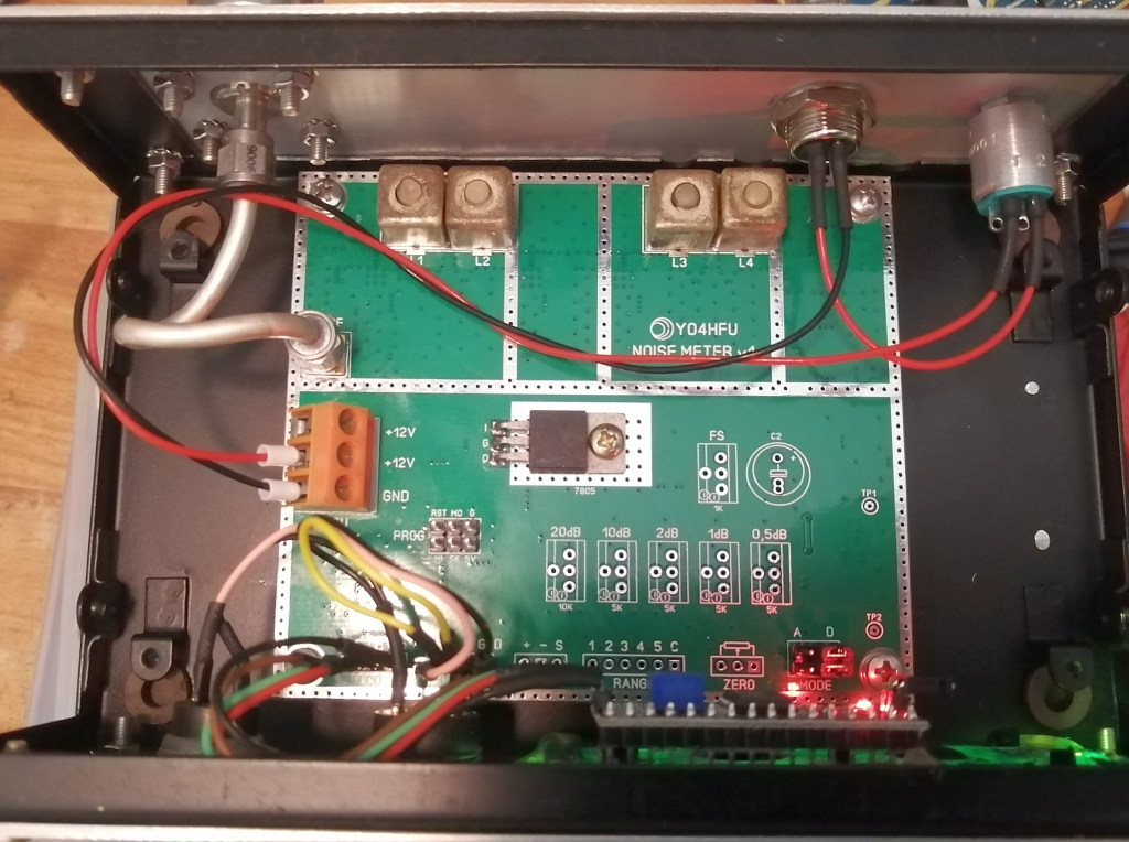
![]() PCB Bottom View (prototype v1)
PCB Bottom View (prototype v1)
![]()
![]() Schematic ver.1
Schematic ver.1
![]() PCB ver.1 (Sprint Layout 6 file)
PCB ver.1 (Sprint Layout 6 file)
![]() ATmega328 firmware ver.5 (8MHz internal clock)
ATmega328 firmware ver.5 (8MHz internal clock)
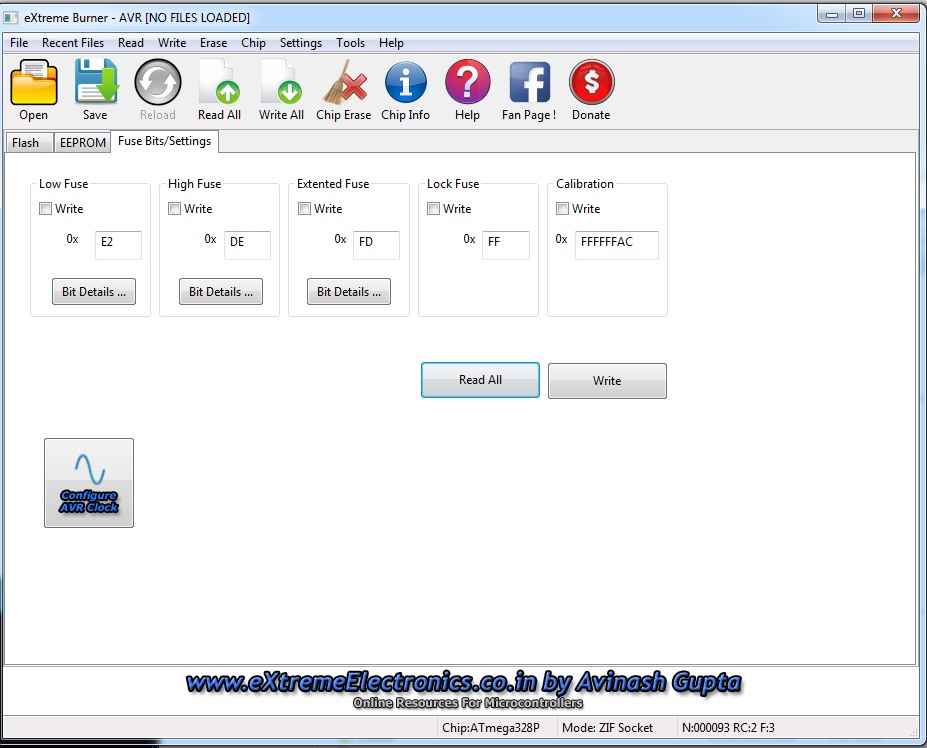
![]() MCU fuse bits
MCU fuse bits