ANTENNA ROTATOR CONTROLLER PWM (YAESU) |

Since I needed a controller for the YAESU G-1000DXC (24V DC), I initially considered the K3NG solution, already quite familiar with it. However, I soon realized it was too complex and the firmware couldn't fit into an ATmega328 (Arduino Nano).
Only azimuth control was required, with operation provided either through a front-panel rotary encoder or computer control via PstRotatorAz software. A version developed by YO3RAK (AZ/EL) and later optimized by ON7EQ (AZ-only) was selected as the basis, then further simplified and modified to meet the specific requirements.
Main Features:
- Azimuth control: 0–360°, with 1° resolution
-
Soft start/stop using PWM control
-
Compatible with Yaesu GS232 protocol, STOP command supported
-
Compact design, internal 24V PSU
-
Automatic calibration using dedicated Arduino sketch
![]() For easier calibration, I have provided a dedicated sketch that needs to be uploaded to the Arduino once, in order to determine the two calibration "AzMin & AzMax" constants that will be manually copied into the main rotor sketch.
For easier calibration, I have provided a dedicated sketch that needs to be uploaded to the Arduino once, in order to determine the two calibration "AzMin & AzMax" constants that will be manually copied into the main rotor sketch.
The results and status are displayed on both the LCD and the serial monitor.
The operation is similar to that of the ARCO controller:
-
The controller moves the rotor in both clockwise and counterclockwise directions while monitoring the signal from the internal feedback potentiometer.
When feedback value no longer changes for a few seconds, the controller detects that the rotor has reached its end limit and has stopped (by the internal limit switches).
The detected signal range is then mapped to 450 degrees, corresponding to the full mechanical range supported by the YAESU G-1000 rotor. Then, the range 0–360 degrees is calculated. -
The controller prompts the operator to enter the actual azimuth of a distant signal source, such as a radio beacon or another station with a known location.
The operator then finely adjusts the rotor position (by front panel encoder) until the received signal reaches its maximum.
The difference between these two values represents the azimuth offset, and all calculations are performed automatically. -
The two calibration constants are calculated, completing the calibration process. These constants must be manually copied into the main sketch that will be uploaded to the Arduino Nano.
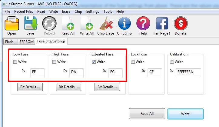
Note: The Brown-Out Detection (BOD) function has increased to 4.3V to prevent EEPROM data corruption. Previously, the last recorded azimuth position value was sometimes corrupted during startup initialization.
Additional materials:
- Arduino Nano
- H Bridge module BTS7960
- LCD 1602 I2C
- Rotary encoder with push button
- PSU 24Vdc, min. 2A
- Enclosure Mouser: 546-1598DSGYPBK
![]()
![]() Rotator PWM schematic
Rotator PWM schematic
![]() Rotator PWM PCB v1.1
Rotator PWM PCB v1.1
![]()
![]() Rotator PWM main sketch v.1.1
Rotator PWM main sketch v.1.1
![]() Calibration Utility sketch v.1 (temporarily used during the calibration process)
Calibration Utility sketch v.1 (temporarily used during the calibration process)
![]() Atmega328 Fuse - BOD 4.3V
Atmega328 Fuse - BOD 4.3V
![]() NewEncoder Library
NewEncoder Library
![]() LiquidCrystal_I2C Library
LiquidCrystal_I2C Library
![]()
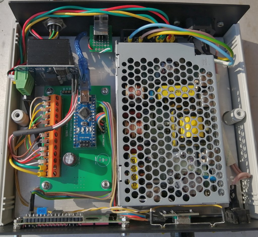
![]() Rotator controller internal view
Rotator controller internal view