EQUIPMENT FOR 144 MHz BAND
Motto: "All sharks were once litle fish"
Rigs: YAESU FT 847 ;
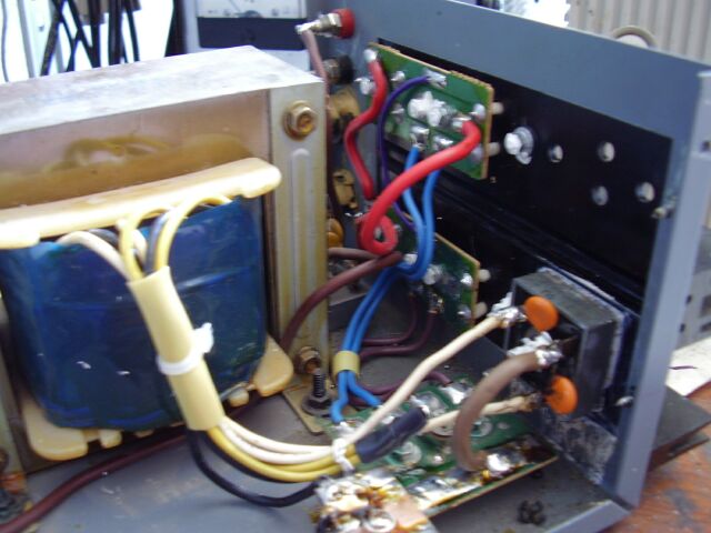
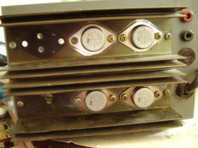
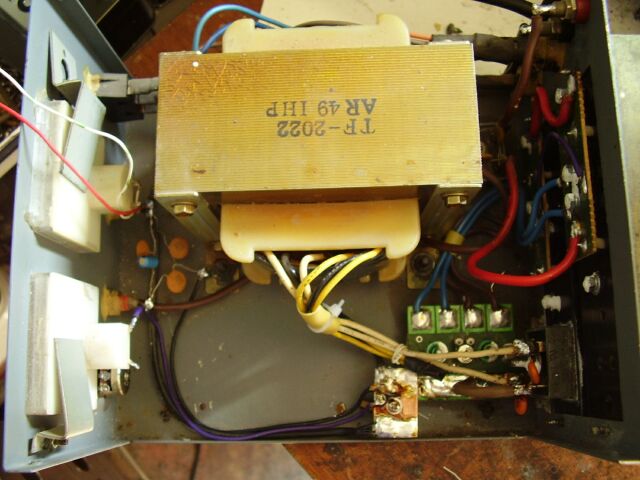
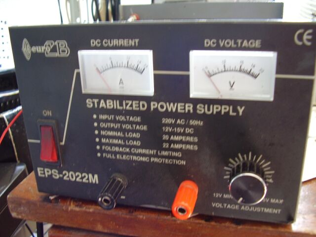
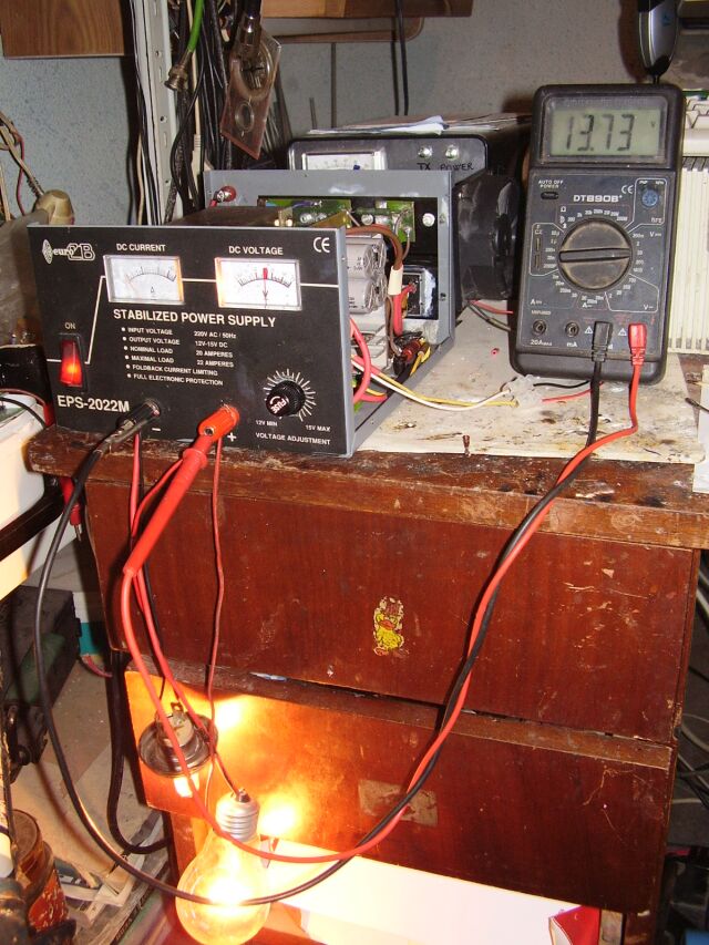
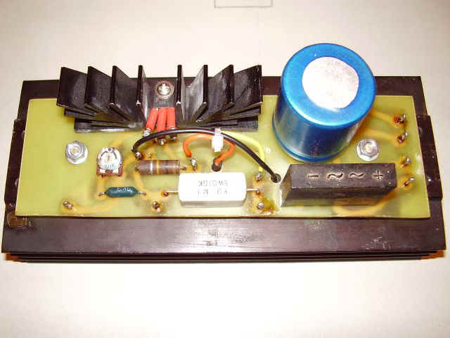
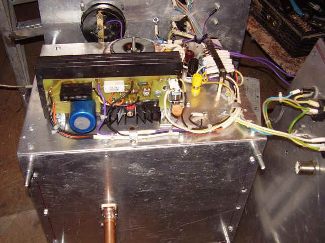
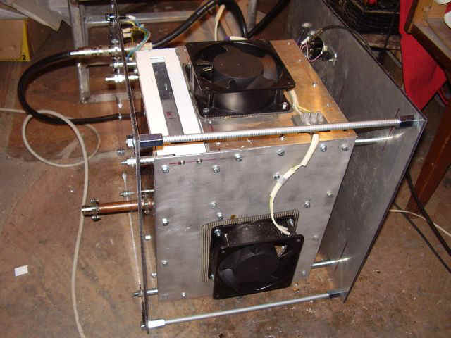
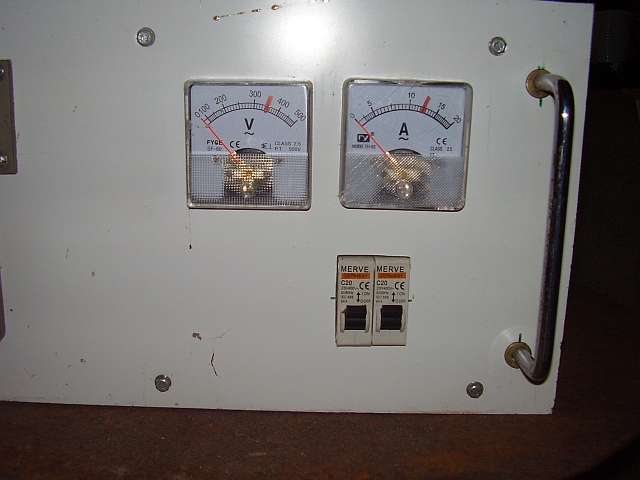
Power Suplly: for YAESU FT 847 - 13,80 Vcc/25A ;
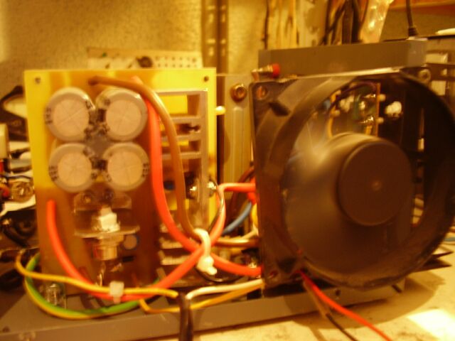
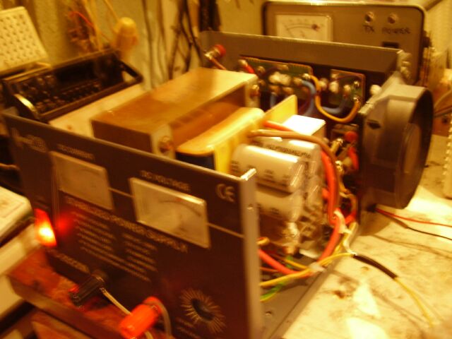
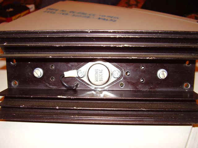
This is a modified professional power supply named EuroCB - type EPS 2022M - which was burned.
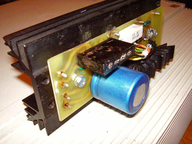
New 25A/13,80 Vcc PSU is based on 7912 circuit application (after YO4GMS plans) ;

Earth Moon Earth (EME) Activity
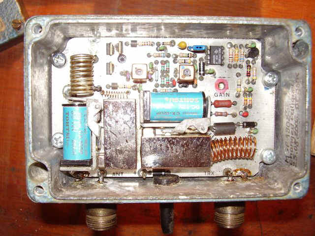
Preamplifier : Ga As (MGF1302) - MWS 144 - SSB ELECTRONICS (coaxial relays included)

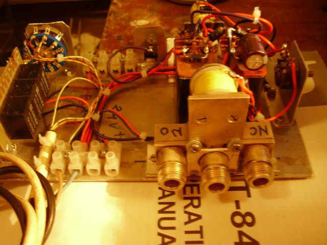
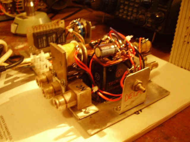
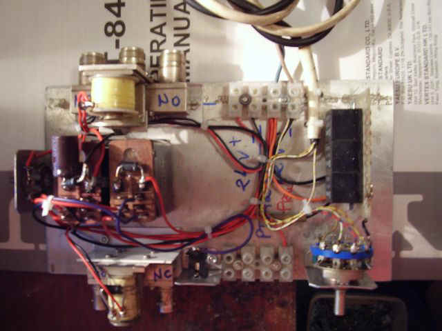
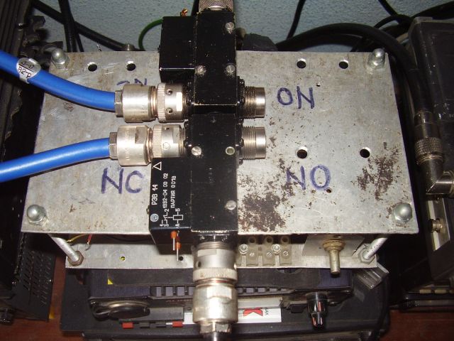
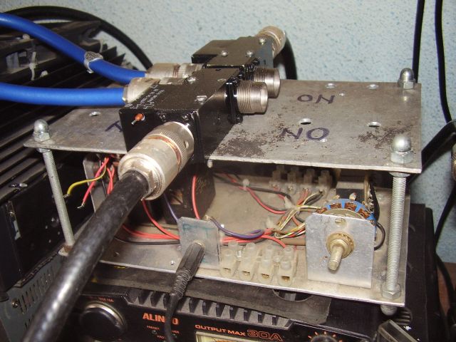
Sequencer : G3SEK design
old version with Tohtsu CX 520D and Amphenol 318-10382-3 relays New version (for big power) with 2 x REW14 relays
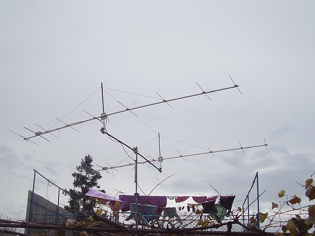
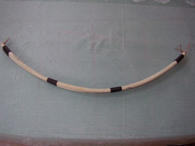
Old EME setup: Antenna system (2 x 9 elements DK7ZB) + dipole details :
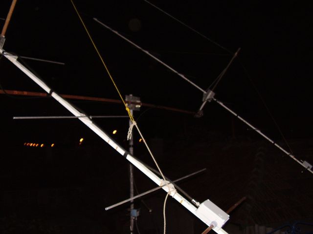
DK7ZB Dipole (home made)
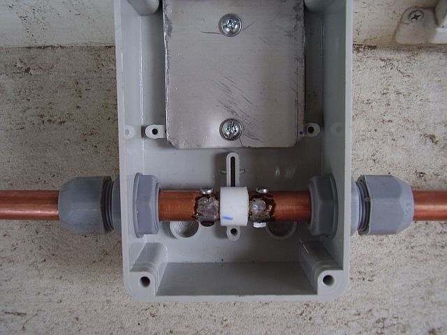
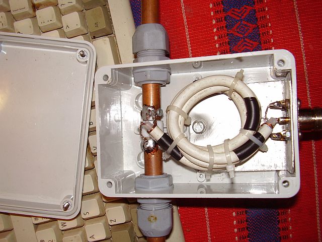
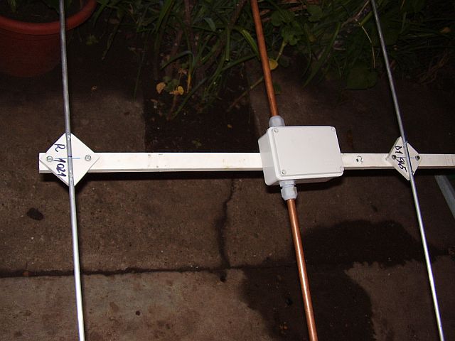
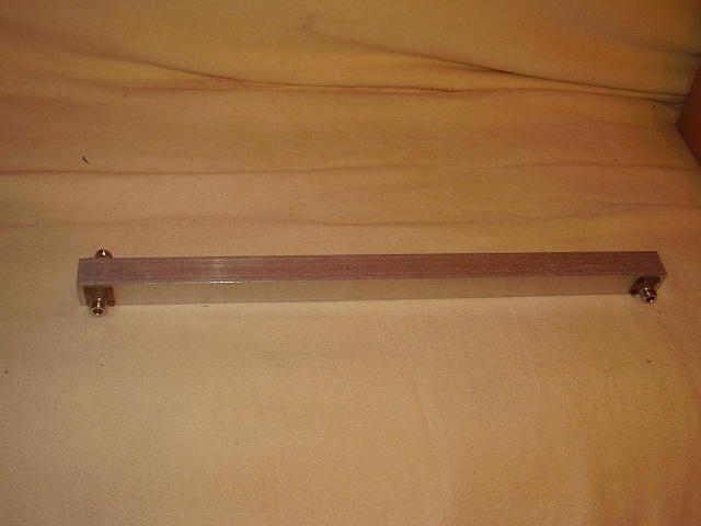
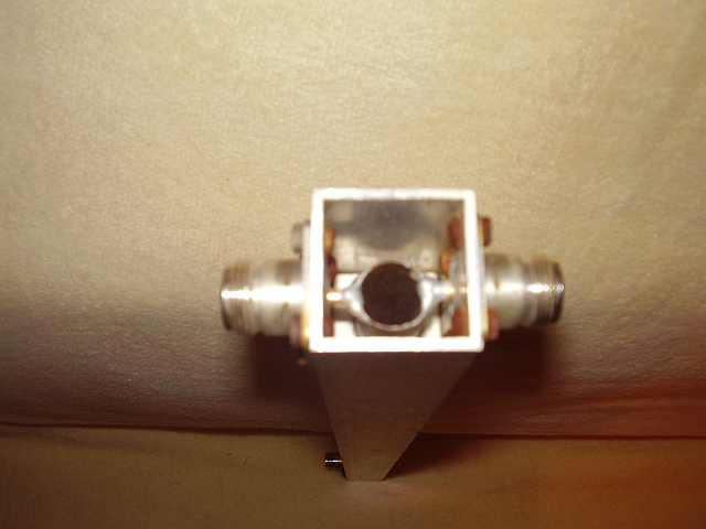
2 way splitter with N connectors (home made)
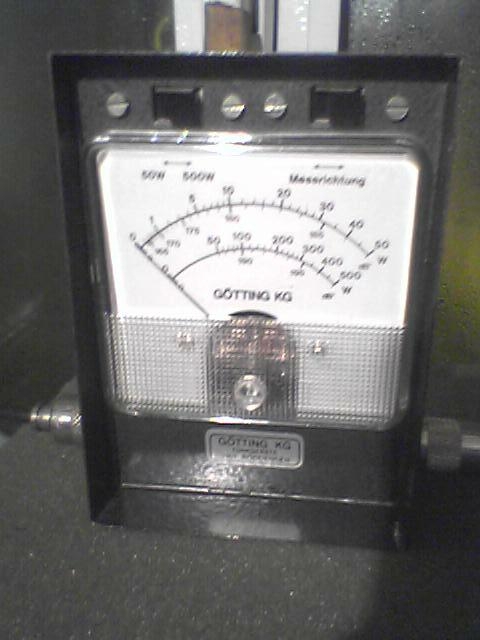
- Gotting KG - 50/500 W (only for 144 MHz band) - used for tropo (Es) and MS ;
- Sx 144/432 K-Po - 10/100/1000 W (dual band, now 1 KW scale it's not longer enough ...) ;

Power Amplifiers :
1. QQE 06/40 - 80 W out ;
2. GI7b - 350 W out (home made after DJ9HO plans);
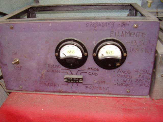
Voltages included into module:
U1 = 13.6 Vca - filament, U2 = 24 Vcc - relays command ;
External PSU( HV) - 2.000 Vcc/500 mA (Io = 100 mA) ;
For 22 W input, 350 W output at 2000Vcc/350 mA ;
This PA it's used mostly in tropo QSO : Es and MS.
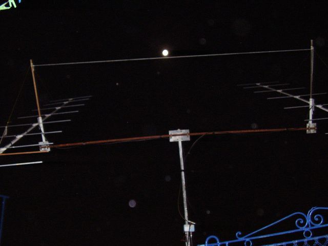
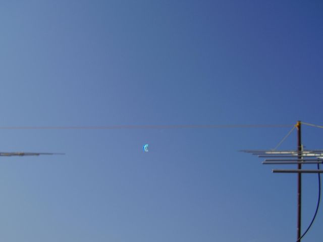
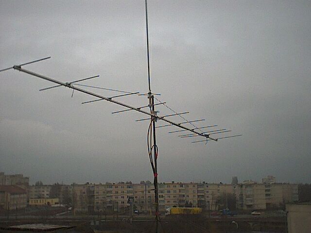
Antenna for MS : 1 x 12 elements DK7ZB (8 m boom lenght) - picture on main page ;
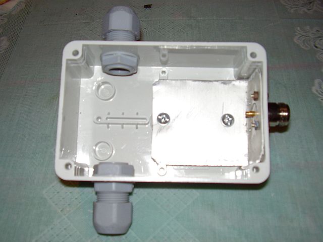
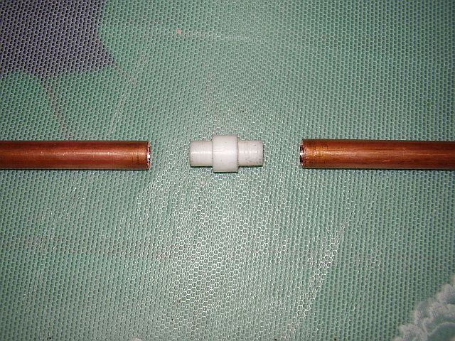
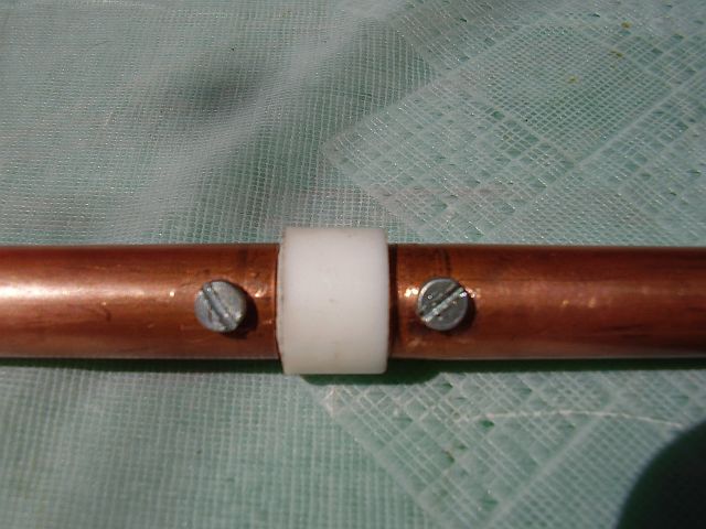
Details for insulated elements mounting for DK7ZB antenna - 8 mm x 1 mm - aluminum pipe mounted on duraluminium pipe
boom (diameter 25mm)
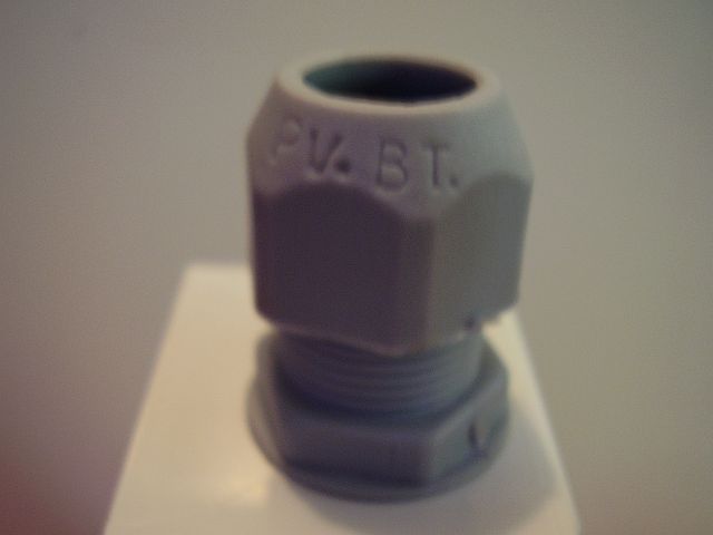
Fixed with plastic elements (Obo Bettermann type 2960/M25 Pg16) - see picture details ;
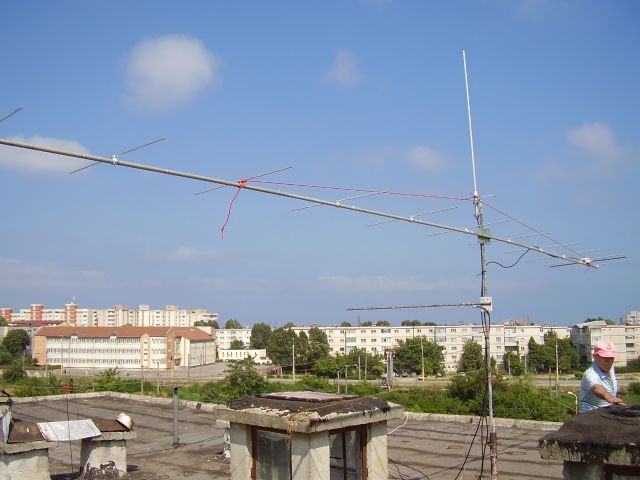


Old 144 MHz antenna - 10 elements DK7ZB (6 m boom) - used in QSO with EA8AVI (world DX distance record - 4293 Km);
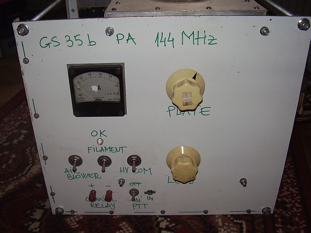
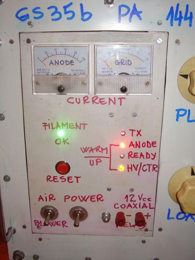
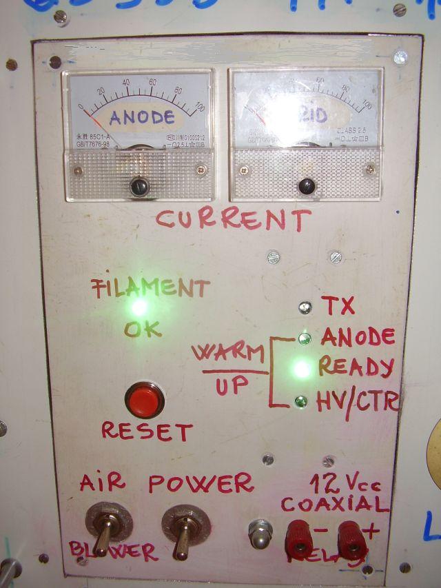
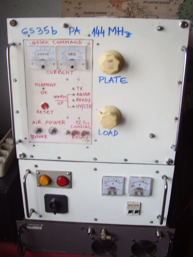
3. GS35b - 1,5 KW out
Remember : Big power, big problems
First GS35b PA version :
special thanks to G4DCV - Paul, for new tube GS35b - as a present for me
- home made 144 MHz - 1 x GS35b PA
- PA was made after DJ5RE plans
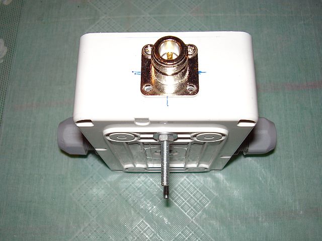
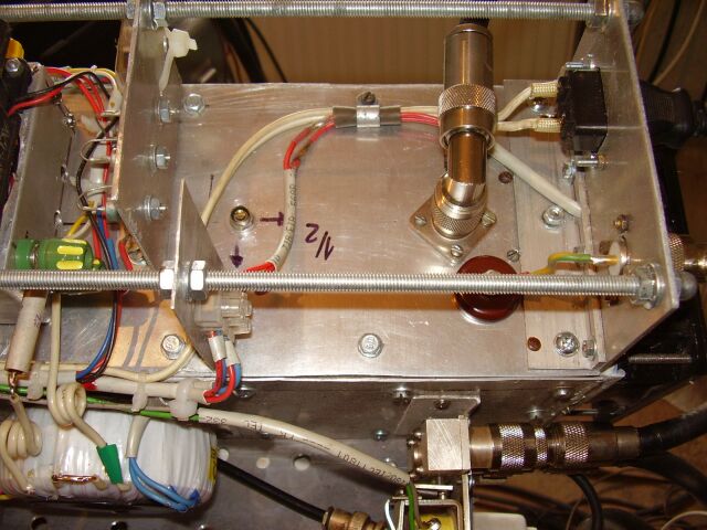
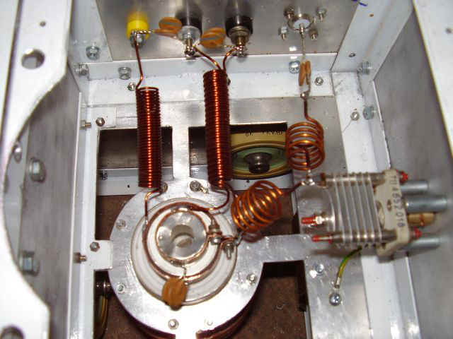
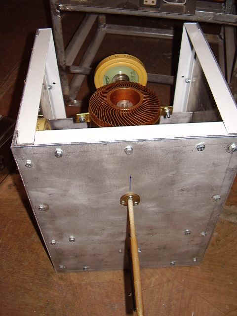
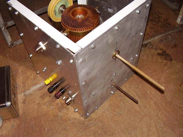
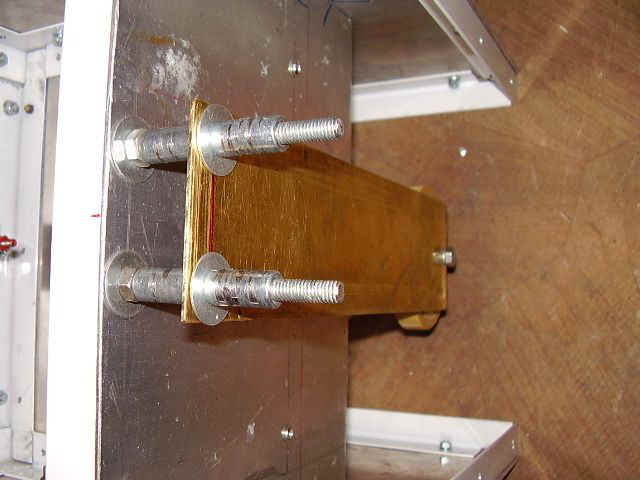
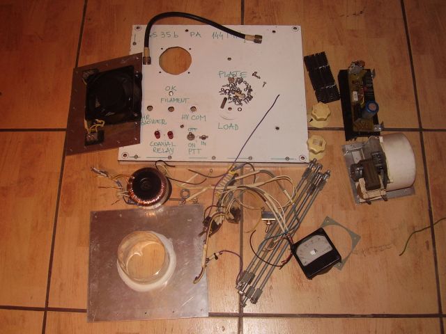
1. Antenna coupler details :
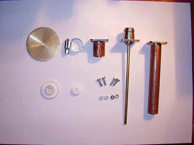
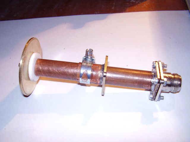

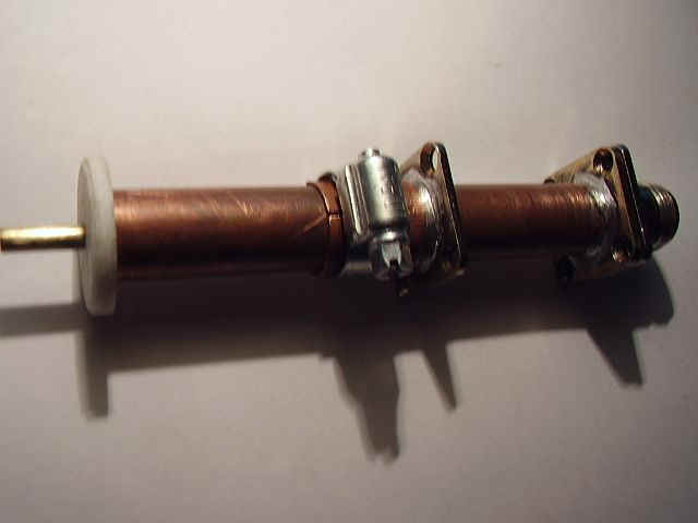
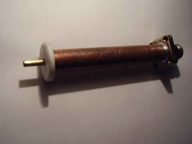
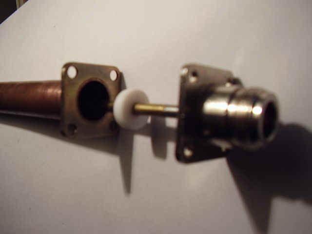
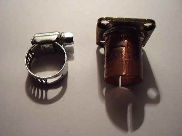
- brass dish : 50 mm diameter/2 mm thick ;
- brass pipe 4 mm diameter ;
- copper pipe 15 mm diameter (from home heat system) and10 cm long ;
- teflon insulators ;
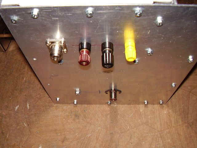
- N connector ;
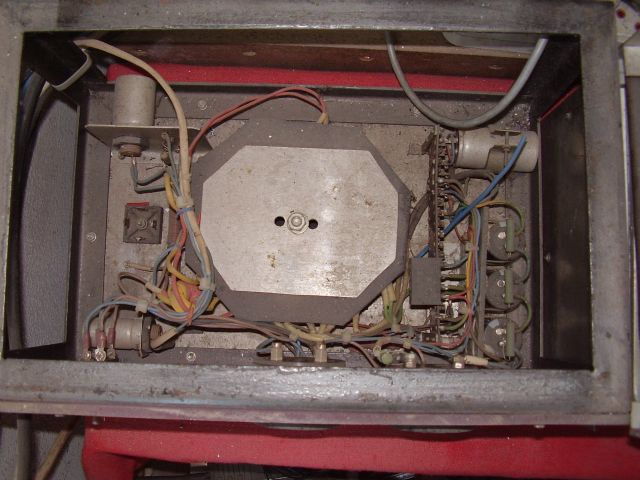
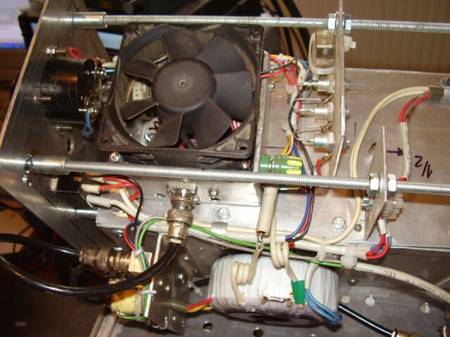
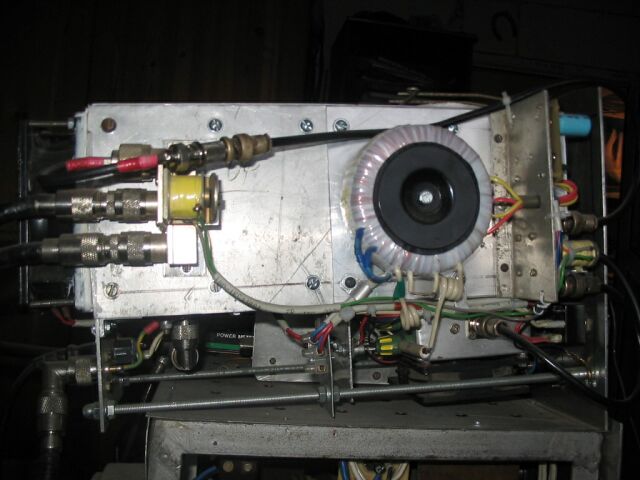
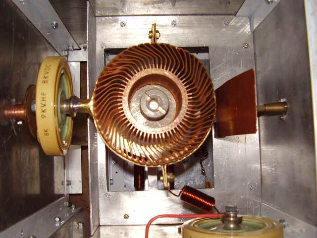
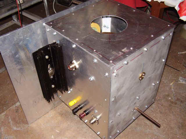
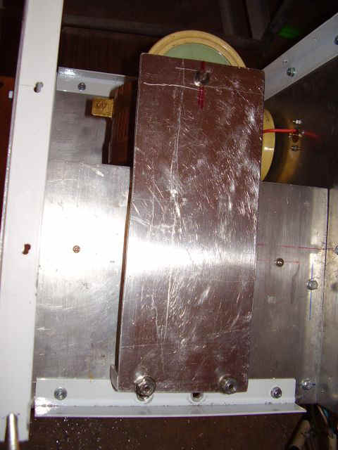
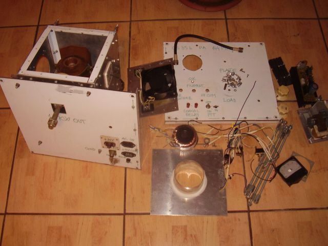
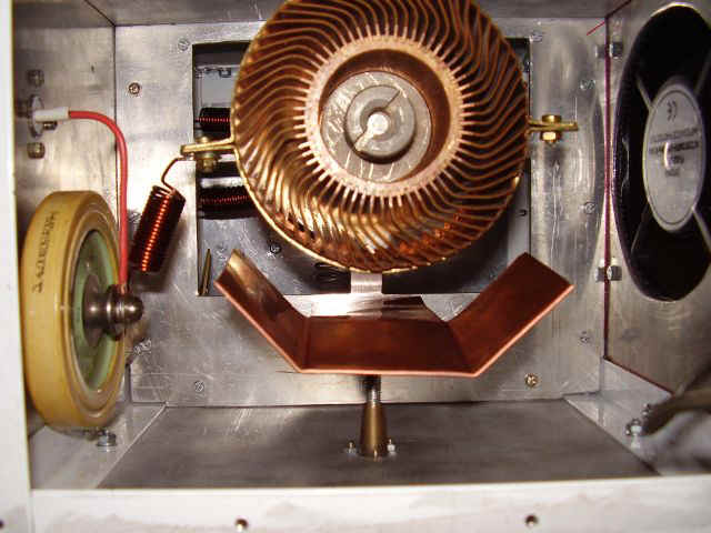
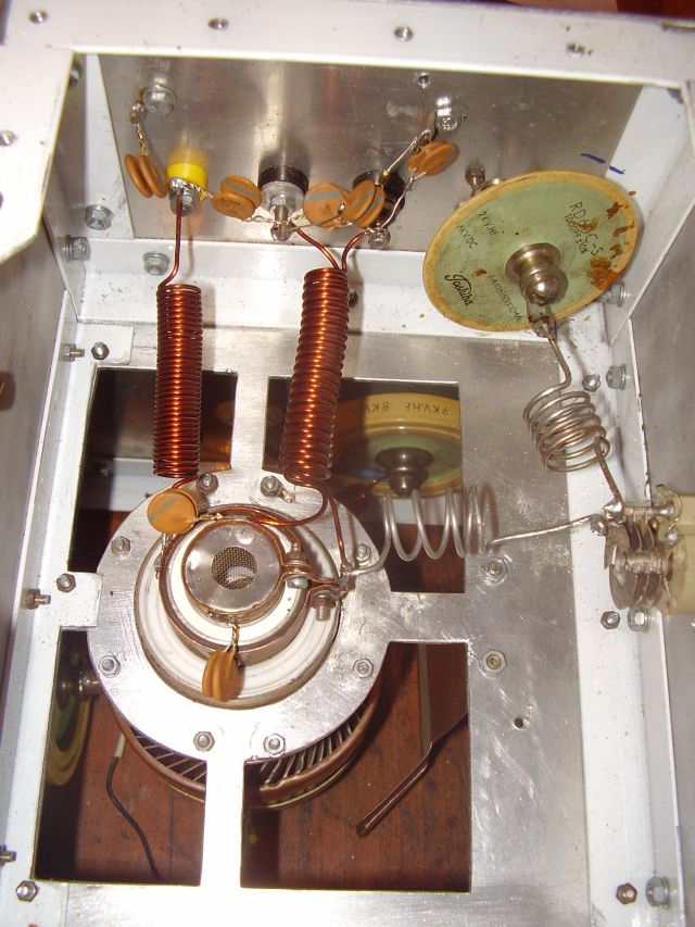
2. Power amplifier cavity

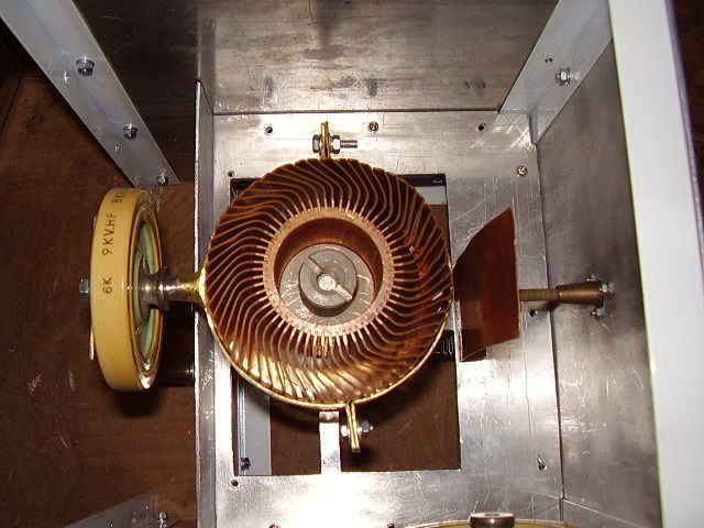
PA assembly

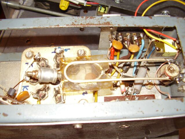
Bias grid supply
Final tests and impression
DJ5RE, made this PA as only theoretical project.
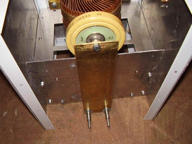
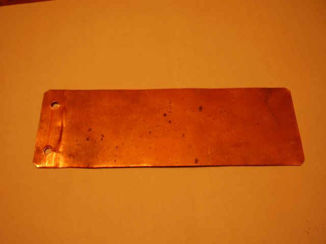
Anode line in original plans is : brass 240 mm x 6 mm x 2 mm ;
I made this anode line as well and the the PA resonance was arround 135 MHz. Values measured with Tesla BM 380 grid-dip meter.
I cut 2 times 10 mm but I can not set the resonance at 145 MHz :
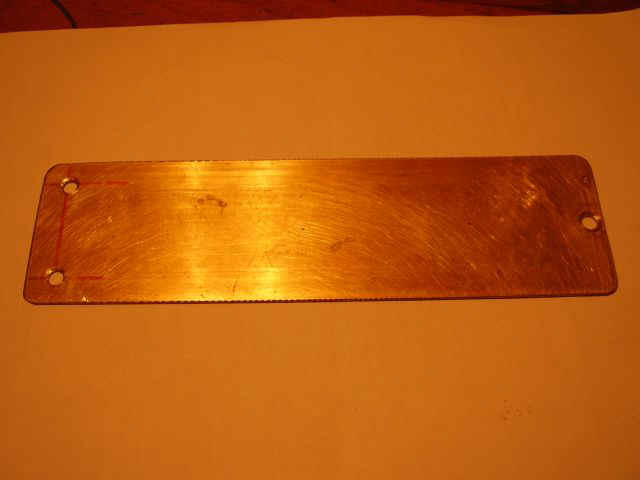
For fix the problem I made second anode line a little bit larger: alluminium 240 mm x 90 mm x 3 mm ;
After the grid-dip measurements the resonance was around 140 MHz. So I replaced the 2 magnetic M6 screws with non metal type and finally the
resonance was set to 145 MHz.
Test Notes: Use only non metal screw type to avoid any problem in frequency settings & alignments.
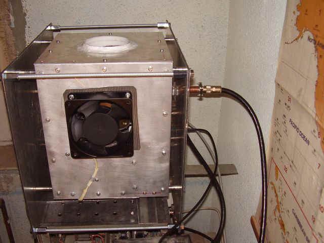
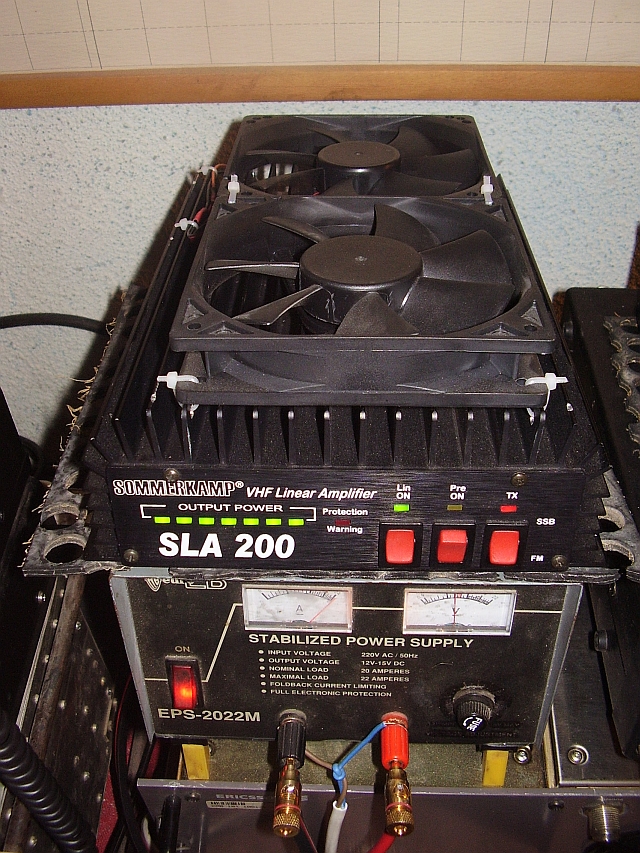
1 - PA's working very good. Used only for EME's QSO. For input have a solid state brick Sommerkamp SL 200 PA ( input for GS35b = 150 W) ;
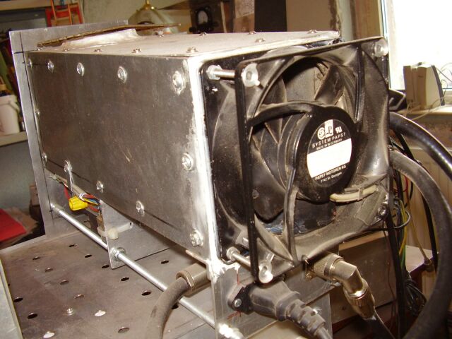
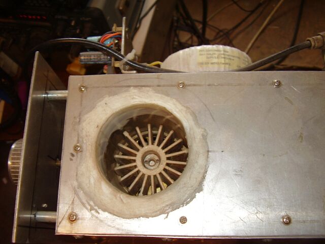
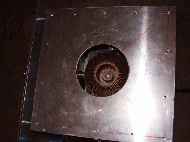
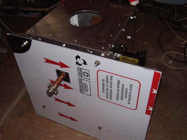
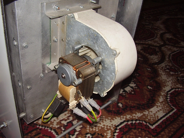
2 - When QSO's in digital modes (WSJT - JT65b) it's not short, or in contests, the tube get very big heat, so I must changed air blower ;
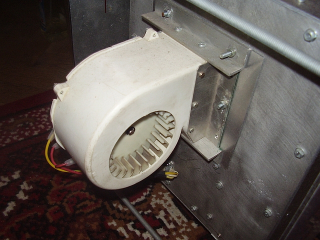
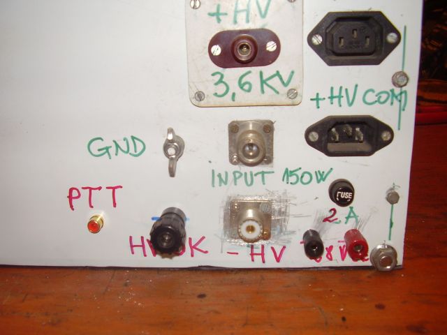
Watch out about HV cables and connectors

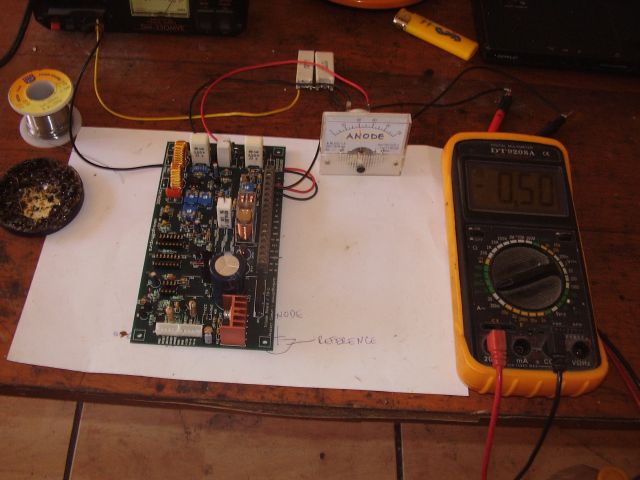
Last GS35b PA version (with triode control board )
I build the triode board control, after G3SEK designs and plans
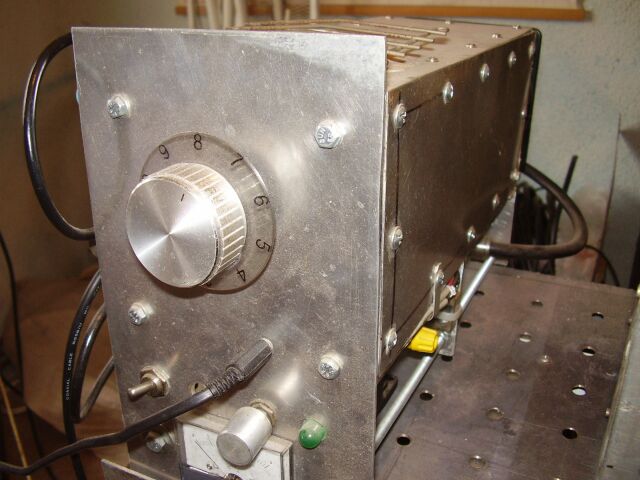
First I made pieces all PA PA into new version rebuilded

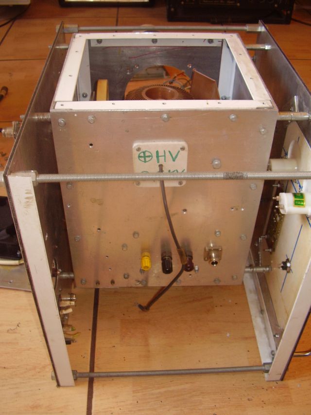
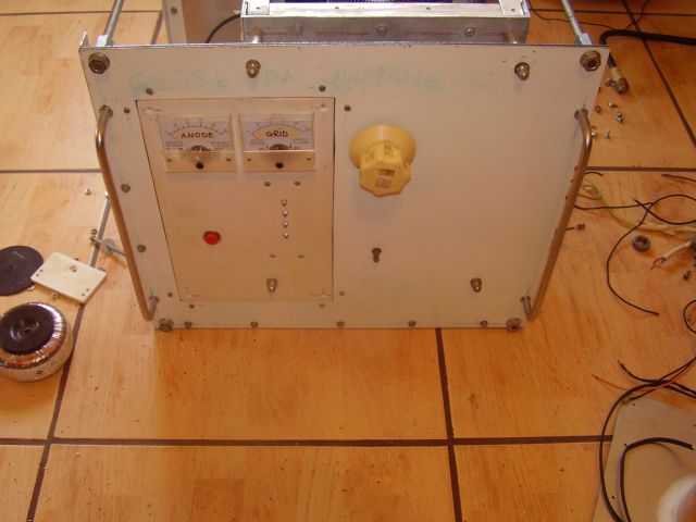
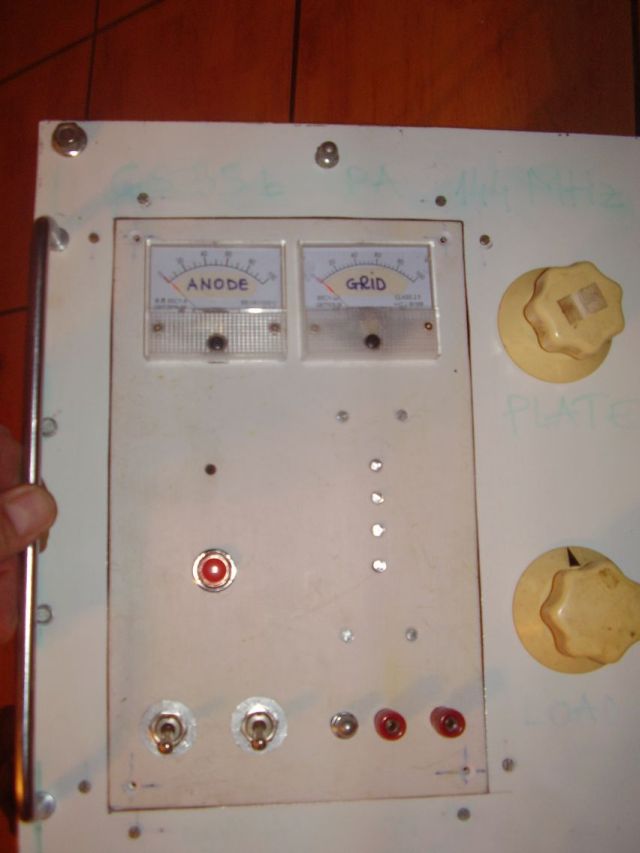
triode board tested and mounted rear panel tests started

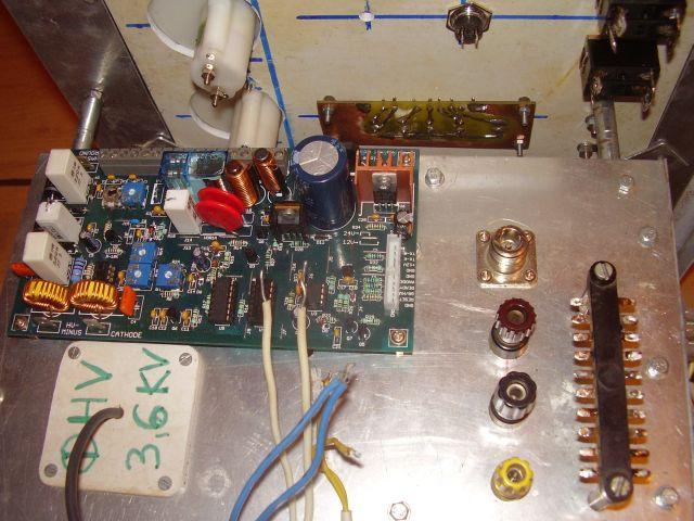
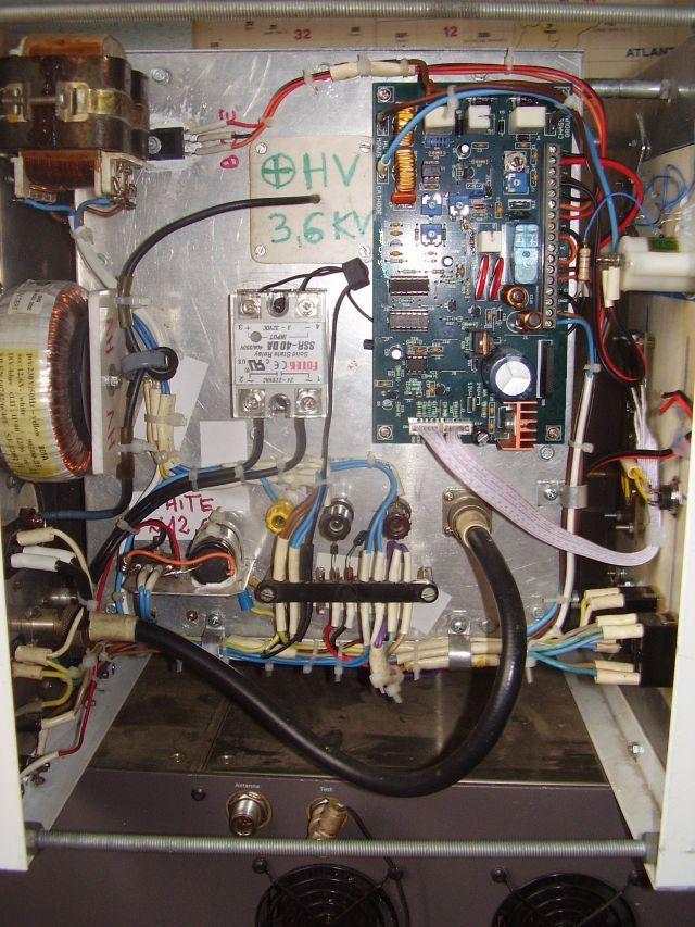
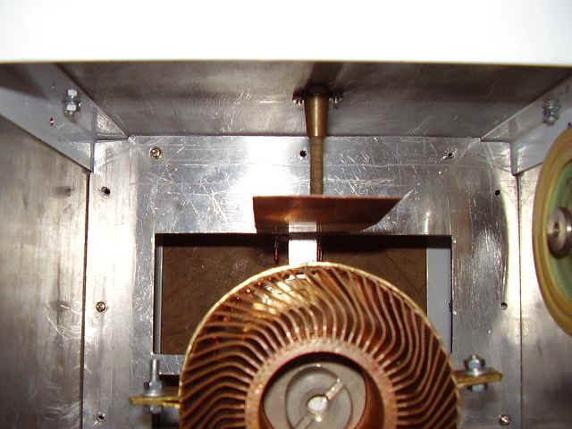
The other problem was that I had not in anode and in input circuits a base point (with minimum and maximum). Redesigned input and anode cavity :
old copper flapper new copper flapper new input cavity And new GS35b PA was born
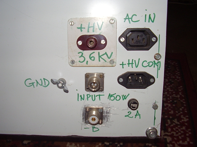
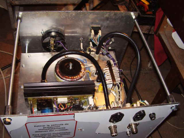
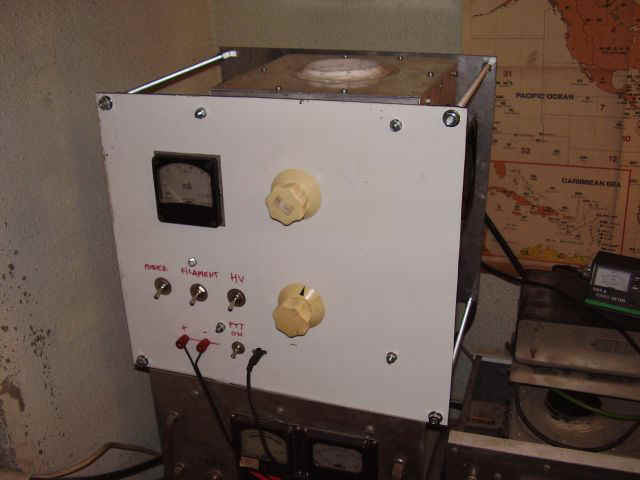
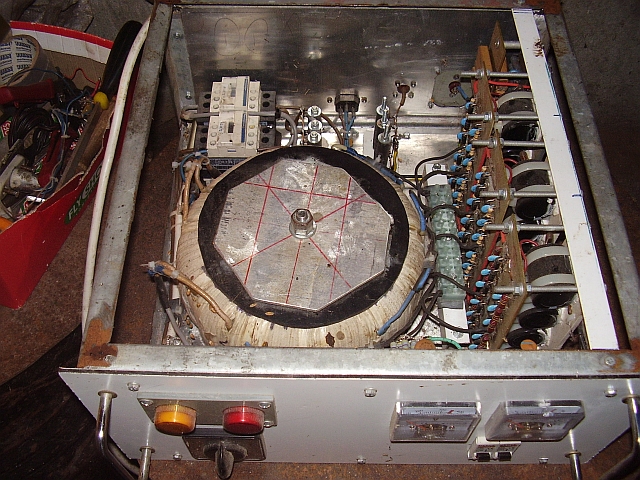
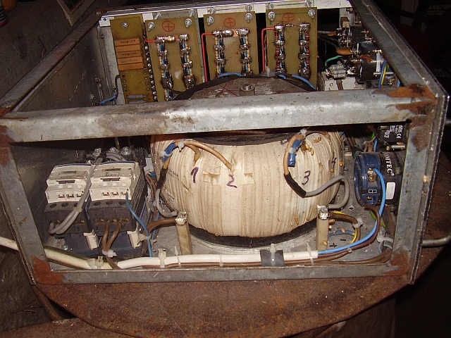
4. HV PSU (3,2 KV/1A) for GS35b PA


- big trafo (18 Kg) with technical details as follow :
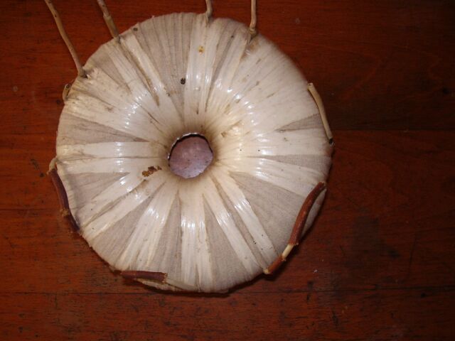
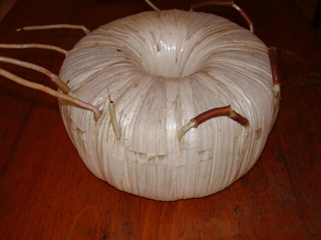
primary circuit : 180/200/220/240 V, secondary circuit : 2 x 370 V + 2 x 740 V (2.200 V) and up to 1A ;
PSU voltage : 2.200 V x 1.44 = 3.200 Vcc ;
Soft start circuits (too big trafo and will burn house's fuse if you'll try to start directly)
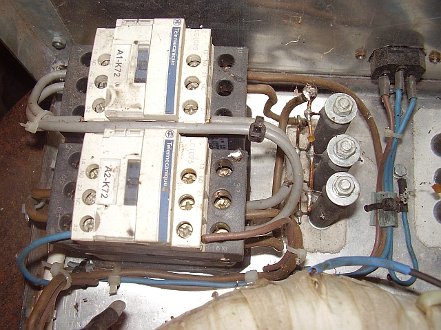
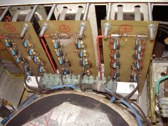
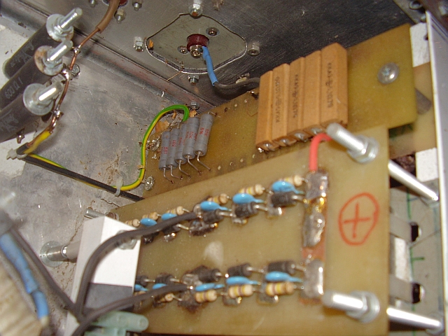
General description : 3 blocks bridge rectifier for up to 1KV each, summed in the end , fused to HV output ;
For HV connectors used RF Millen Parts/USA type safe to 18KV/4A ;
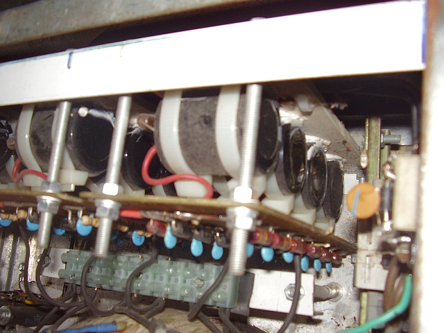
36 diodes 1000V/3A, 15 capacitors x 470 micro/450V, 36 x resistors 470K/2W and 36 capacitors x 1n/2KV ;
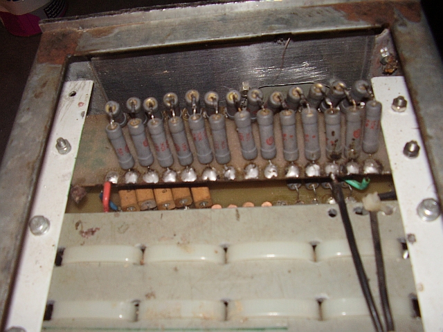
Bleeder : 36 resistors x 10K/5W summed ;
Glitch block : 5 resitors x 10 ohms/17W summed ;
PSU made grounded grid type : 3 resitors x 200 ohms/25W ;
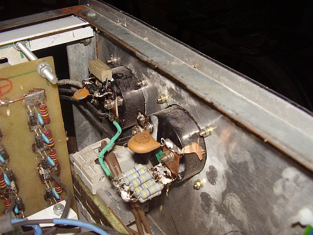
SPECIAL NOTE
Take care about HV cables and connectors. I use special cable (18 KV) and special connectors (18 KV/4A), made by RF Millen Parts/USA.
This is not joke and HV can easy kill you.
To be able to use the old version HV PSU with new GS35b controlled by triode board had to made some modernizations
01.07.2009
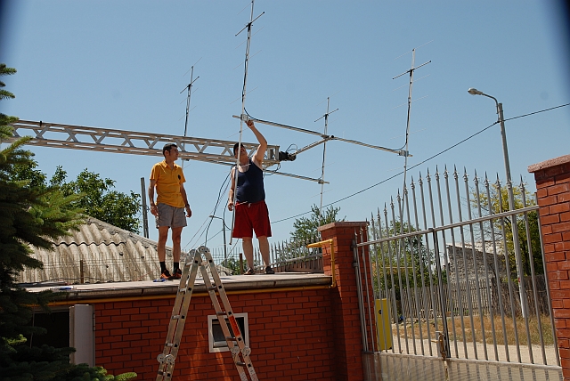
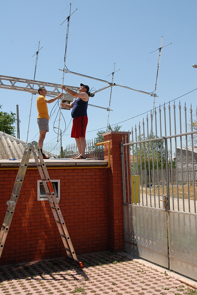
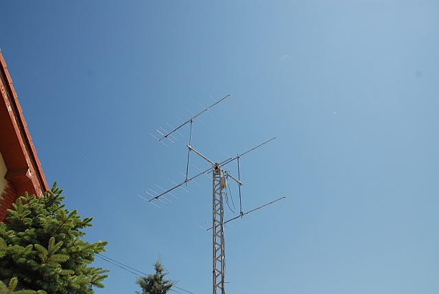
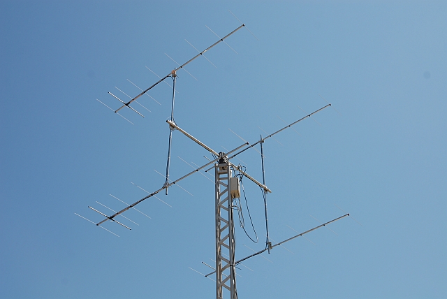
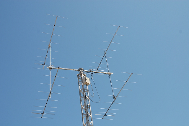
New EME's base for contests (into YO4ASV's George location)
4 x 9 elements F9FT and YAESU G-5500 full Az/El rotator mounted on 10 m high tower
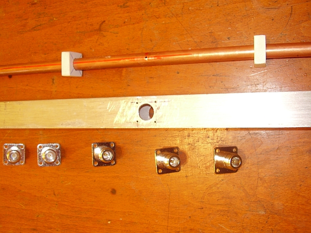
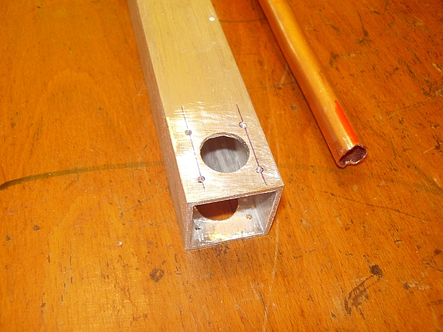
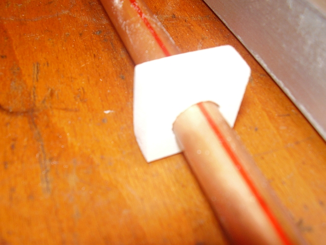
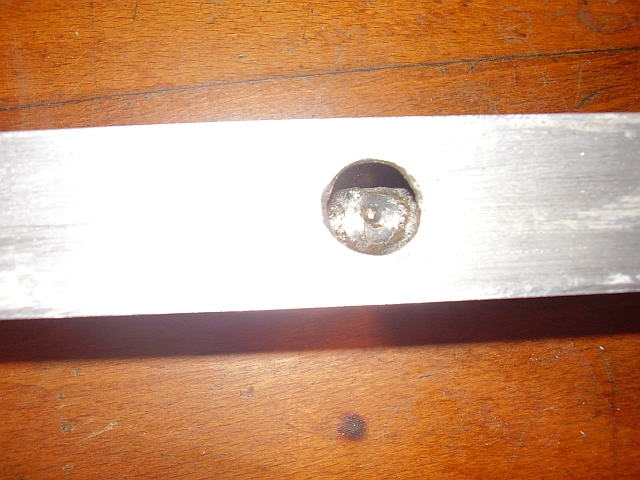
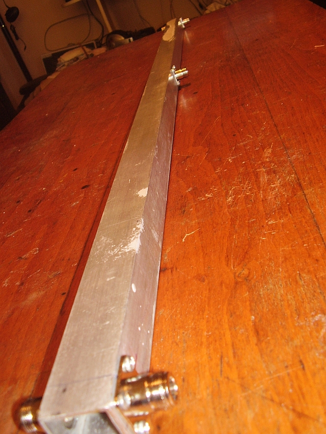
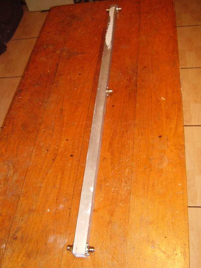
4 way power splitter - home made
30 mmx 30 mm x 2 mm - aluminium square tube and 12 mm diameter inner copper pipe
26 x 26 teflon (10 mm thick) - 4 pieces for insulate the inner copper pipe


Again QRV via EME