![]()
![]()
![]()
![]()
![]()
![]()
![]()
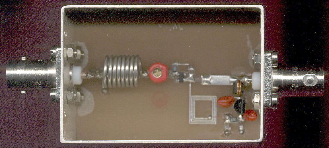
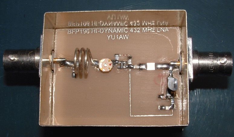
BFP196P
BJT by Infineon
or
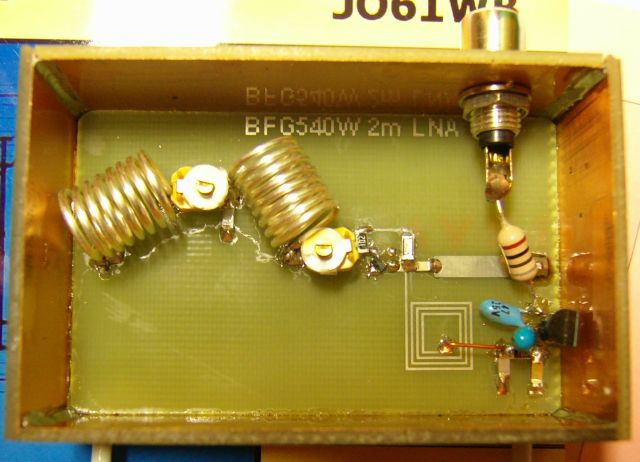
BFG540X
BJT by Philips
Published in Radio T9 magazine

(text in Serbian)
Ultra Linear (High Dynamic)
Low Noise Amplifiers (2001.)
Article in English (2.2 MB PDF file)
![]()
![]()
![]()
Gain, IP3in, IP3out, NF
-----------------
50 MHz 70MHz 144 MHz 222MHz 432 MHz 1296 MHz


 50MHz
50MHz 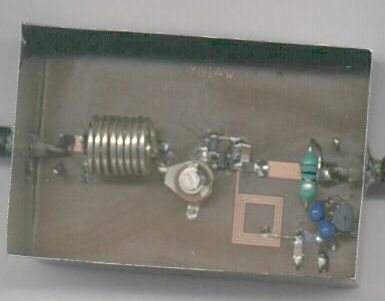 144MHz
 432 MHz
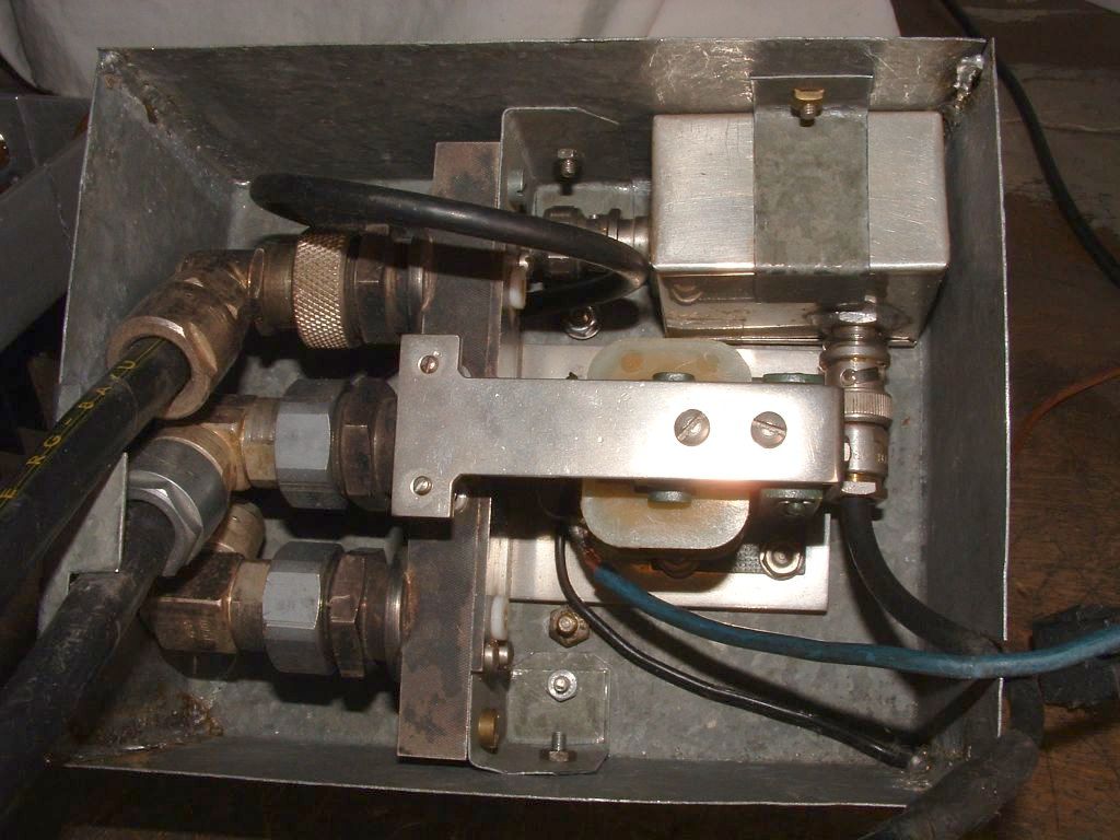
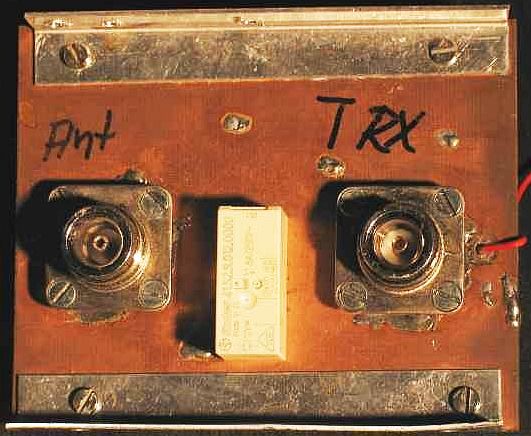
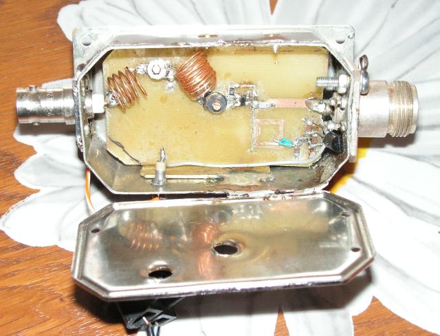
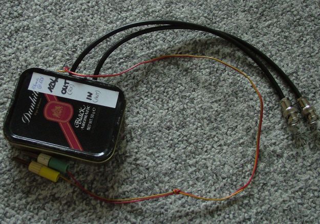
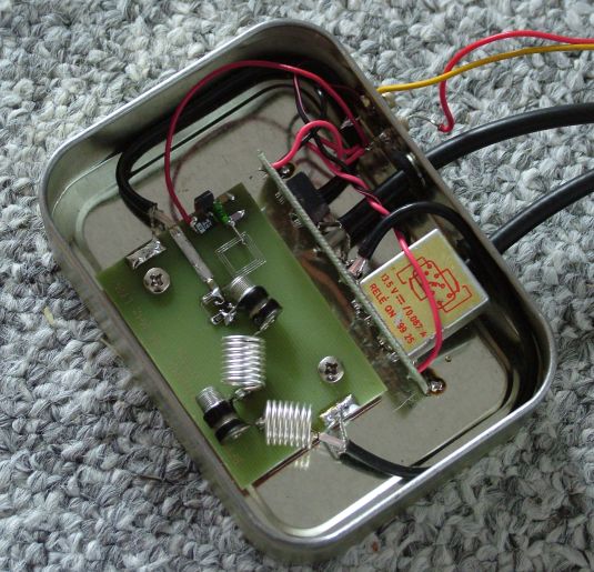
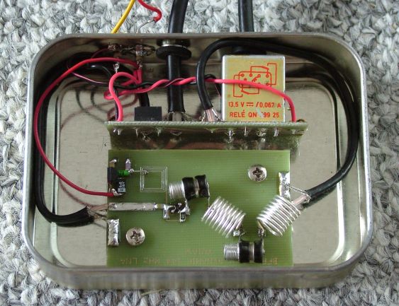
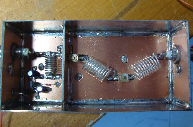
Preamp "in site" with ant. coax relay
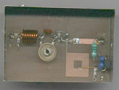
Built by Saša, YU1EO
Built by Paja, ex YU2XO:
 144MHz
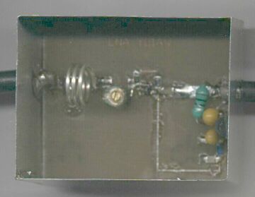
Built by: Paja, ex YU2XO i Dragan, YU1GC
 432 MHz
 144MHz
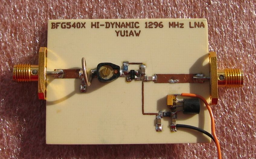
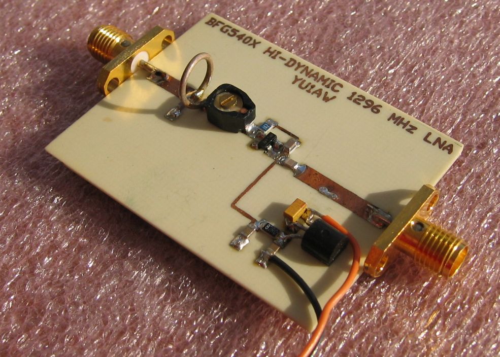

 1296MHz
Built by: Adam, 9A4QV

![]()
 144
MHz
144
MHz
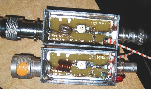 144
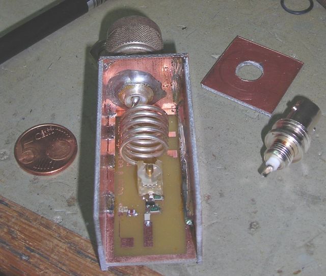
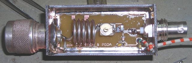
& 432 MHz
144
& 432 MHz
Built by: Remco, PG0A and PF0A


AutoCAD files in DWG format for Printed Circuit Boards:
BFP196 50 MHz - PCB BFP196 70 MHz - PCB BFP196 144 MHz - PCB
BFP196 222 MHz - PCB BFP196 432 MHz - PCB BFG540X 1296 MHz - PCB
All PCBs made of 1.6 mm double side FR4 or G10 epoxy (Er=4.8). Back side left as ground plane.
All used SMD components are type 1206.
AutoCAD files in DXF format for Printed Circuit Boards:
BFP196 50 MHz - DXF BFP196 70 MHz - DXF BFP196 144 MHz - DXF
BFP196 222 MHz - DXF BFP196 432 MHz - DXF BFG540X 1296 MHz - DXF
Low Noise Amplifiers
with improved input selectivity! (2003.)
![]()
![]()
better selectivity with new input circuit
-----------------
Built by: Mike, DL6IAK
 144MHz
Built by: Philippe,
F4AVP
 144MHz
Built by: Steffen, DD0VF
 144MHz
Built by: Jan, OK1TIC - 144MHz
 50 MHz
Built by: Alex, IK0VAQ
http://ok1gth.nagano.cz/lnabfg540.pdf
Built by Tomáš, OK1GTH for 144 & 432 MHz
*****
How to tune preamp?
First trimmer to the antenna, Ct1,
changing loading of second circuit and, as you can see on simulations pictures,
change overall selectivity and NF, but it does not change resonant frequency.
So there is no resonance peak when you tune Ct1!
Second trimmer, Ct2, tune resonant frequency. Both trimmers influence to NF, but
second trimmer, Ct2, keep good NF at new resonant frequency. First trimmer, Ct1,
doesn't change resonant frequency, but change selectivity and NF very much!
Please, tune trimmer, Ct2, to best
reception at frequency you want by listening some very weak signal. Then, trimmer Ct1 tune at
same capacitance as first one. Both trimmers have to be close to calculated
capacitance value given
on schematic diagram if parasites of coils are not too big. Tuning is not very
critical and by following suggested tuning procedure you will tune your preamp
very close to minimum NF value! By this, all other calculated performances will
be also achieved.
As illustration how tuning capacitances of Ct1 and Ct2 influenced gain and NF, I
made some computer simulations on 70cm preamp.
![]()
![]()
![]()
![]()
You can see on pictures what happened with gain and NF when you change
capacitances of one trimmer from its nominal value of 2.2pF (for 70cm band
preamp), to 1.2pF and 3.2pF, while other one is kept at its optimum value of
2.2pF.
*****
AutoCAD files in
DWG format for
Printed Circuit Boards:
BFP196 50 IS - PCB BFP196 144 IS - PCB BFP196 432 IS - PCB
All PCBs made of 1.6 mm double side FR4 or G10 epoxy (Er=4.8). Back side left as ground plane.
All used SMD components are type 1206.
AutoCAD files in DXF format for Printed Circuit Boards:
BFP196 50 IS - DXF BFP196 144 IS - DXF BFP196 432 IS - DXF
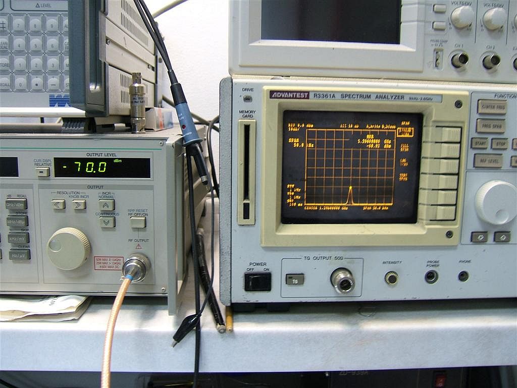
Which amplifier is better for contests?
In order to check how amplifiers will behave in contests I conducted some simulations. GaAs FET MGF1302 and BJT BFP196 amplifier were fed with three strong signals ("three strong stations on 2m band") 7.1 mV (-30dBm) each, at its input. Results are given below, showing what would be heard with ideal, linear receiver (no receiver IMD!) under such conditions, and very obvious superiority of BFP196 preamplifier.
MGF1302 IMD test BFP196 IMD test
![]()
![]()
![]()
![]()
![]()
![]()
![]()