DC-DC converters
On this page I present two different DC to DC converters I have built,
for two totally different purposes: To power a VCR from a car battery,
and to light a model airplane glow plug from a 12V starter battery.
The VCR converter: 12V to 120V, 20 Watt
Many modern pieces of home electronics, like video recorders, have switching
power supplies that can accept any voltage from about 90 to 250V AC, at
frequencies of 45 through at least several hundred Hertz. But it is less
known that most of these power supply can perfectly well accept DC voltage
too! That DC voltage should be at a level of close to what the AC peak
would be, that is, typically this equipment will accept about 110 to 320V
DC.
I live in a place where sometimes we get power cuts. It does not happen
really often now, but when it happens, I hate having to re-program the
memories and timer of my video cassette recorder! It looses memory as soon
as the power outage lasts for more than a few seconds. But I have a large
storage battery in my radio room, under constant charge, and given the
low power consumption of a VCR, I decided to put it on the battery. I looked
inside, and tried to inject a backup voltage into the CPU circuitry, but
having no schematic diagram I missed the proper spots, and the machine
always kept forgetting everything. So I decided to power the entire VCR
from the battery, through the AC power input.
The most obvious approach would be to make a DC to AC inverter, having
110 or 220V AC output at 50 or 60 Hz, but this requires a rather large
and heavy transformer. So it's better to use a high frequency, at least
25kHz, so a very small and cheap transformer can be used. But sending 25
kHz into a power supply designed for 50 to 60 Hz is no good! The input
diodes are not fast enough, and the noise filter at the input would place
a heavy reactive load on the inverter! So I decided to rectify the secondary
voltage in the converter, and power the VCR with DC.
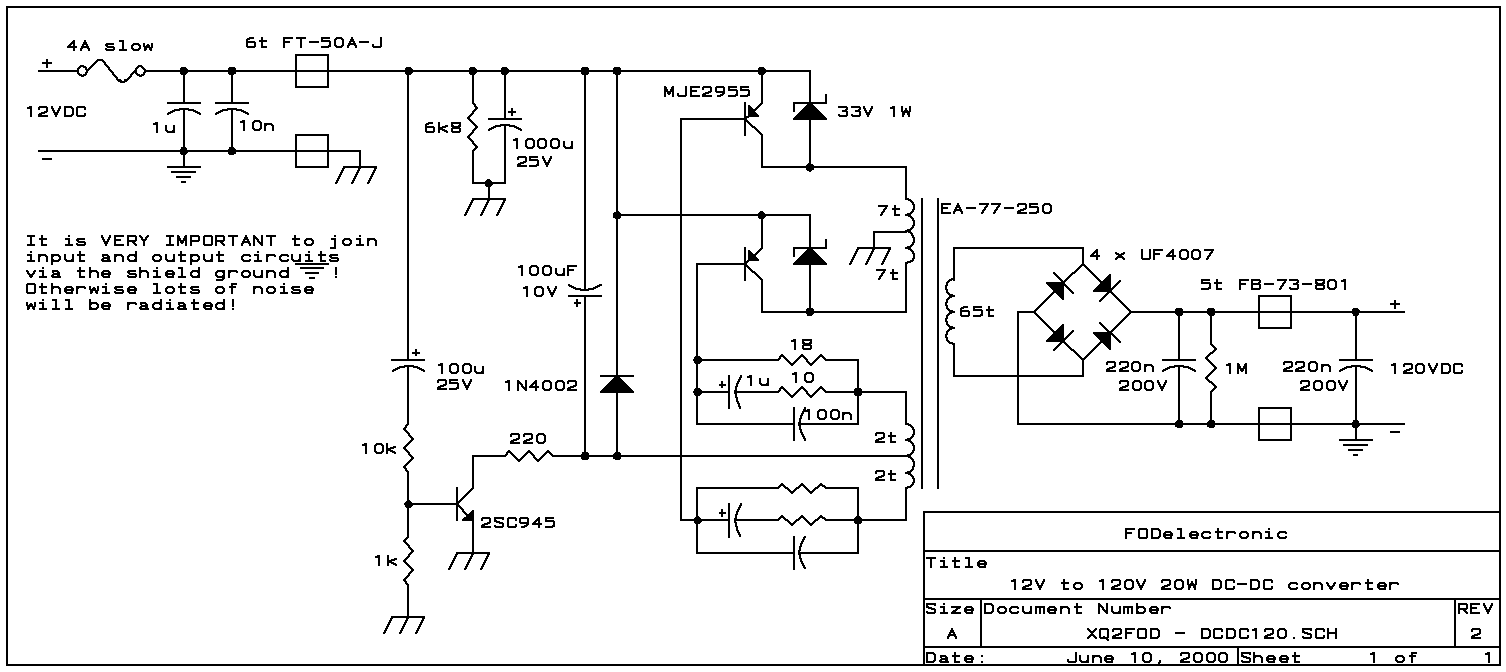
 Here is the schematic.
You can get the full resolution version too.
The design is a simple saturation-limited push-pull converter. There is
no special reason to use PNP transistors; I used them simply because I
had a box full of them around. You may well turn over the design to use
NPN transistors.
The 2SC945 is a bias switch for startup. When applying 12V power, this
transistor applies enough bias to the power transistors to get the oscillation
started. Soon later, the 100uF capacitor charges up, the transistor goes
off, and the power transistors self-bias into cut-off, such that cross-conduction
is eliminated. After removing power, the 6k8 resistor discharges the bias
timing capacitor, as otherwise the circuit would be unable to restart!
The secondary rectifiers are ultrafast diodes. These are NOT 1N4007!
And the 220nF capacitors for the secondary filter are no typos; the diodes
deliver almost pure DC, since the oscillation waveform is square, so only
some noise filtering is needed. No electrolytics are necessary here.
Note the filters at both input and output, using ferrite cores. These
are necessary to avoid polluting your environment with RF noise! Using
these filters, and joining the input and output negative leads, this converter
is very quiet and does not cause any problem in my combined HF, VHF and
UHF station.
All ferrite cores (for the transformer and for the noise filters) are
manufactured by Amidon Associates, and can be ordered directly from them
in small quantities. Look for Amidon on the web. The 77-material core used
for the transformer is less than ideal. A square-loop ferrite would work
more efficiently! This one gets really warm, operating in saturation mode
at 25 kHz. But it has worked well enough for two years now. The filter
cores, on the other hand, are well chosen, so try to use the exact ones.
For all windings, the schematic states the number of turns. "7t" means
7 turns. As the transformer is quite small for the involved power, use
as thick a wire as you can fit, leaving about half of the space for the
2x7 turns primary winding, and the other half for the secondary, while
the feedback winding can be made from very thin wire.
The transistors do not need any heat sinks. They are large enough without,
and they need to dissipate little heat!
The glow plug converter: 12V to 1.5V, at 4A
Model airplane engines usually are of the glow plug variety. Such a glow
plug needs about 1.2 to 1.5V, at a current of several Ampere. Many model
fliers use single NiCd cells, but these are a bit weak for the task, and
as soon as an engine becomes a little bit stubborn, the battery quickly
runs down. But most modellers use 12V starters to get their engines running,
so they anyway need a 12V battery, or at least they need to steal 12V from
their cars! The idea is not new to use this 12V supply for the glow plug
too. But dropping off the excess 10.5V in a resistor would require a large
resistor that would get really hot, and it would waste a lot of energy.
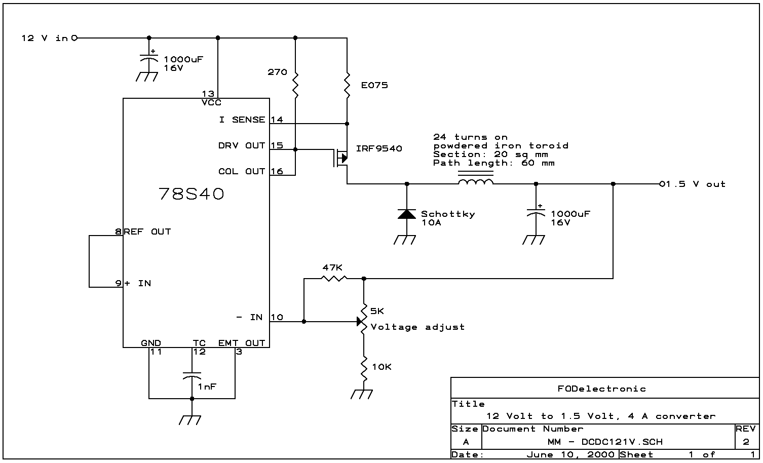
Here is a DC to DC converter that performs this task much more efficiently.
 As in the other
case, here is a full resolution version for
you.
The 78S40 is a very old, but still useful power conversion chip. It
contains a 1.25V reference, comparator, gating, output transistor, flyback
diode and an uncommitted operational amplifier, which is not used here,
and draws very little power. As the internal transistor and diode are good
only for 1A maximum, I had to use external parts instead. Even so, the
circuit is simple enough! A P-channel MOSFET was used as power switch,
and an unknown toroid from my junk box was pressed into service for the
filter choke. The circuit works very well, with an efficiency of better
than 60%, which is superb for such a low voltage output!
I assembled the entire circuit, complete with power switch, in a small
aluminum box measuring 4x4x6cm. The MOSFET and the diode were bolted to
this box, for heat dissipation. The diode will dissipate around 2W at full
output, so it would get too hot when free running. The MOSFET would probably
have no trouble, as it dissipates much less power.
If you don't need adjustable output, and are happy with a fixed 1.25V
output, you can eliminate the trimpot and resistors around it, and connect
pin 10 directly to the output.
The circuit is fully short-circuit protected. The 0.075 Ohm resistor
sets the current limit. If you have trouble locating such a low value,
place the proper amount of higher value resistors in parallel!
Back to the homo ludens electronicus
page.
 Here is the schematic.
You can get the full resolution version too.
The design is a simple saturation-limited push-pull converter. There is
no special reason to use PNP transistors; I used them simply because I
had a box full of them around. You may well turn over the design to use
NPN transistors.
 As in the other
case, here is a