 Perhaps the most
basic instrument needed for flying is an altimeter. I had built several
of them by the time I took up flying, simply because I started mountain
climbing much before, and altimeters are very useful for that sport too.
But for free flying, something better than just a basic altimeter is needed:
There should also be a variometer function built in, that is, the instrument
should measure rate of climb/fall, and give acoustic information about
this.
Perhaps the most
basic instrument needed for flying is an altimeter. I had built several
of them by the time I took up flying, simply because I started mountain
climbing much before, and altimeters are very useful for that sport too.
But for free flying, something better than just a basic altimeter is needed:
There should also be a variometer function built in, that is, the instrument
should measure rate of climb/fall, and give acoustic information about
this.
There are many such instruments available commercially. But for an avid
home builder, it's just too boring to call a dealer, shell out several
hundred dollars, and wait for the factory-made instrument to arrive. It's
very much more interesting to built one at home, and considerably cheaper
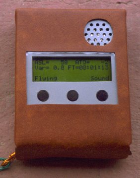
too! This photo shows the end product of a design, development and construction
effort that was completed in just two months of partially devoted spare
time. Duplicating this design is of course very much faster.
Electronic pressure sensors work in much the same way, only that there is no friction involved. A very small hole is etched in a silicon chip, evacuated and sealed. The top cover is formed by a very thin silicon roof, which deforms elastically under varying air pressure. Some resistors are etched into the silicon cover, and these change their values according to the stretching or contracting of the silicon surface. Now it's just a matter to read the values of these resistors, to get a very accurate representation of absolute air pressure!
Many such sensors are available. They vary from the simplest ones (just those resistors on a silicon vacuum cell), to some that include temperature compensation, to some that have a complex signal conditioner on board, to those that give direct digital output. I have tested about half a dozen of different brands, and finally selected the Philips/Valvo KP131 as my preferred device. It provides an output from 0 to 5 Volt for pressures of 0 to 1200 hP, is quite accurate, small, and not overly expensive. And it has no quirks or strange behavior, like some other sensors do.
My first tests were centered around an analog circuit, with a digital display for altitude and a needle meter for variometry. But I had severe trouble with the circuits necessary to produce the variometry reading, and the logarithmic converter needed to convert from air pressure to altitude was not very elegant. And then, I wanted to add more features... So, I quickly made up my mind to include a microprocessor in this instrument.
To cut on development time, I decided to use the Parallax Basic Stamp II. This is a small microcomputer based on a PIC microprocessor, that comes with an on-board sort-of-BASIC interpreter and an EEROM. It is very easy to work with, needs very little power, and while it is not specially powerful compared to other microcontrollers, it is good enough for this rather simple job.
As a display, I chose a Matrix Orbital 20 character by 4 line LCD module
that features a one-line serial interface.
Let's start at the upper right corner. You will see a rechargeable battery composed of six NiCd cells of 600 mAh, fuse-protected, which power this instrument for about 20 hours on each charge. Above them is a simple current regulator, which acts as a charging regulator, accepting anything from 10 to 20 V at the charging jack. So, you can use a battery eliminator, wall wart, or a cable wired to your car's cigarette lighter, to charge the internal batteries. A LED has double duty as voltage reference and charge indicator. Do use a red LED, no other color, or you will be changing the charge current! The voltage drop across a LED depends on its color! Charge time is 15 hours for totally empty batteries, and moderate overcharging doesn't do damage.
Now have a look at Q1, Q2 and associated circuitry. These are the ON-OFF switches. At first, Q2 is biased off, and the entire instrument will be off, with no discernible current drain from the batteries. When the right button (SW3) is pressed, through D2 this switches Q2 on. The 5V regulator (U4) will receive power, and the Basic Stamp will start up. The first thing the software does is enabling the output at pin 11, thus switching on Q1, which in turn holds Q2 on and keeps the instrument powered, regardless of the status of SW3. To switch the power off, the Basic Stamp has to shut down pin 11, thus committing suicide by removing its own power! All this is an elegant electronic scheme to avoid a simple mechanical power switch! I don't like mechanical power switches on such instruments, because it is too easy to unwillingly trip them.
The three pushbuttons now are read by the Basic Stamp, and are used to perform several functions (more on this later, in the section about the software). For now let's concentrate on the hardware.
Look at the lower right. There is the KP131 pressure sensor. It couldn't be easier to use. It gets 5V power, ground, and outputs the pressure signal, buffered and ready for use! Just a small parasitic suppression network is added there. Now pay attention, as things get complicated: Pin 14 of U2 is an output, pin 13 is an input. To start an altitude acquisition cycle, the Basic Stamp switches pin 14 low, and then waits for pin 13 to go high. U7A is a Schmitt-trigger timer, and will wait for a small amount of time, so the Basic Stamp can prepare internal measuring routines. Then U7A will switch its output high, the Basic Stamp will sense this on pin 13, and start counting time. At the same time, Q4 will stop conducting. It had previously charged C8 to the full 5V. Now C8 will discharge in a logarithmic curve, while U7B compares the instant voltage on C8 to the pressure output of U8. When the two meet, U7B will pull U2's pin 13 down. The Basic Stamp stops counting at this instant. This is a simple way to acquire an analog value without using an A/D converter! But this is not the only nice thing: The logarithmic curve of the capacitor discharge is exactly in step with the logarithmic ratio between atmospheric pressure and altitude! So, while the VOLTAGE at the KP131's output is proportional to PRESSURE, the TIME count acquired by the Basic Stamp is proportional to ALTITUDE!
Did you like this? I came up with this design as a workaround for the fact that the Basic Stamp does not have logarithms built in, and not enough memory space for a conversion table. The result is cheap and effective. As Thomas Edison said, inventing is a combination of brains and material. The more brains you use, the less material you need!
The only thing remaining is doing a linear gain/offset adjustment, which
is easily done in software.
The rest of the circuit is simple: U5 and U6 form an interrupted oscillator (which produces a "beep-beep-beep" type sound). U2 can switch it off an on through pin 20, and can vary both the beep rate and frequency to any of three values, by setting pin 19 to high, low, or off. This oscillator drives a small speaker, that gives audible indication of climb or fall.
U3 is there for a quite silly reason: The Basic Stamp provides no timing function that could be used while doing other work. But I need timing, both for variometry calculation and for the flight time counter (an unnecessary, but useful function). So I added U3 as a 1-second timer. The entire software is synchronized to this external clock. While a quartz oscillator and divider would have been more precise, a carefully adjusted 555 timer is OK for this application.
The display, a Matrix Orbital LCD2041, receives serial data from the Basic Stamp, and is powered from the 5V bus. No more care is required for it. It works very well.
P1 is the programming connector. You can built the entire instrument,
and then load the software into EEROM from any PC, through this connector.
By adding proper software routines, this same connector could be used in
flight to transmit real time information, receive GPS data, or any other
purpose you come up with.
---------
UPDATE: It seems that by 2001 the KP131 pressure sensor has become
unavailable. But there are several other sensors on the market, which should
be able to replace the KP131 without any disadvantage. The most easily
found of these seems to be the Motorola MPX4100A. Its casing is totally
different, so you will need to modify the board or bend some wires to make
it fit, but electrically it should work without modifications. Anyway,
it may be good to change C9 to 470pF and eliminate R28 (using a jumper
on the PCB), in order to provide the termination suggested by the manufacturer.
You can download the data sheet and a lot of additional information from
the Motorola site, doing a search
there for "MPX4100".
---------
All the other components can easily be bought locally.
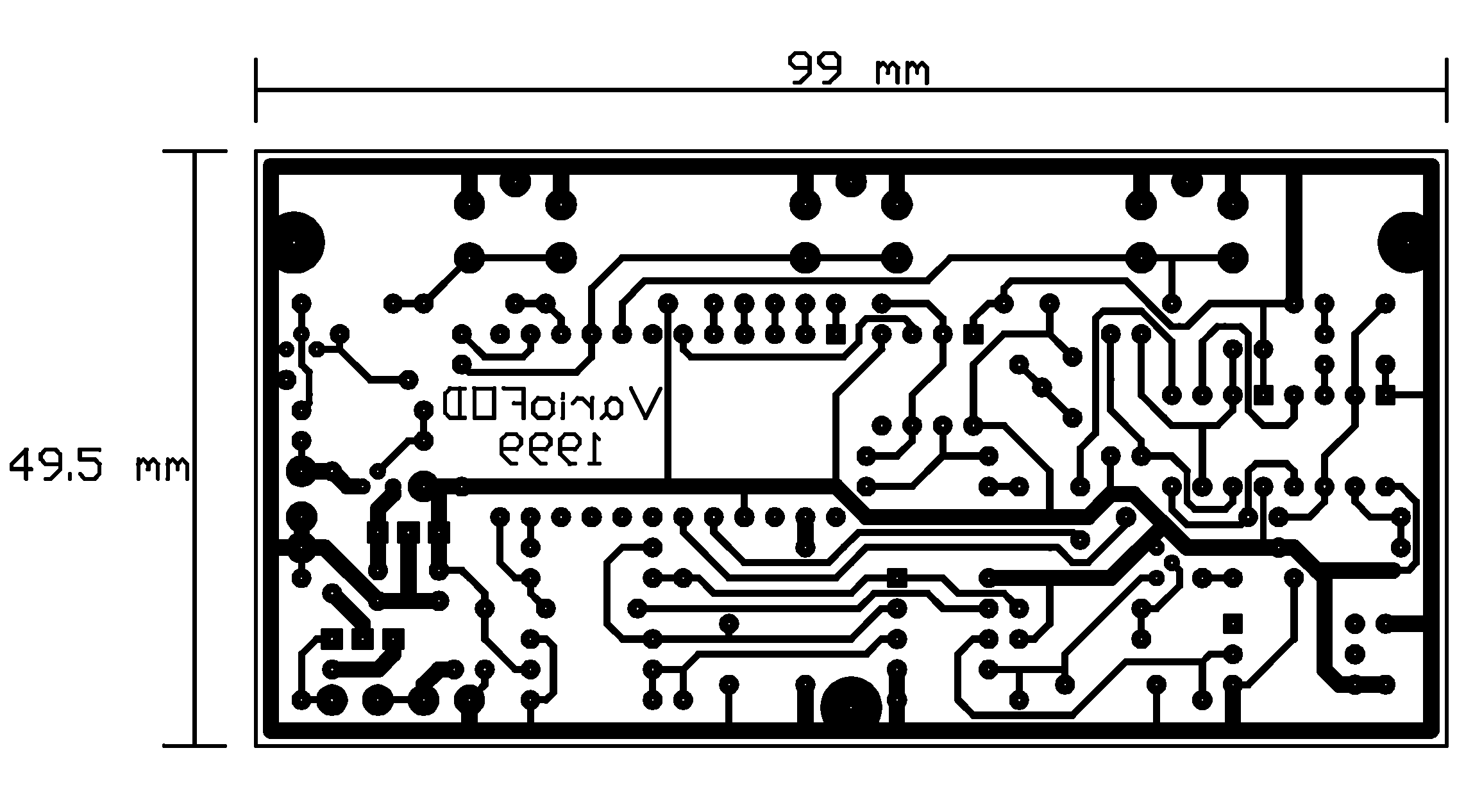
Here is the copper pattern for the printed circuit. As all my PCBs, this one is seen from the components side, so, if you print it out on transparent material, you can place it ink-down on your PCB material. Exact dimensions are given, to avoid any doubts. Depending on your software, you may have to scale the print to end up at the proper size.
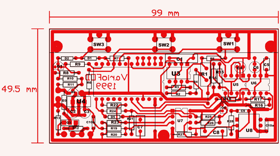
Here is a detailed component layout diagram, which was worked out and contributed by Laurent Lecoutre during the process of building his version of the instrument. Note that the three pushbuttons are mounted on the solder side! The assembly is very easy to do. Be sure to use a good quality plastic capacitor for C8. Once complete, you can power the circuit up and adjust the R1 to have the pulses at U3, pin 3 at exactly 1 Hz. That's the only hardware adjustment!
The completed PCB is screwed to the display unit, components down, buttons up, such that the area of the PCB that carries the buttons uses the space left by the LCD on its carrier board. This allows to make a very compact assembly.
I made an enclosure for my instrument from 1mm aluminum sheet,
which I tailored precisely around the size of the display, PCB, batteries
and speaker, ending up with an instrument that is more compact than some
commercially built ones. Then I made a vinyl carrying case, that has the
proper attachments for a leg strap mounting, as commonly used by paraglider
pilots. An additional safety rope is attached directly to the aluminum
case, to avoid dropping the instrument if the leg strap comes loose.
I added some comments to the program, and used sensible variable names,
so you should be able to follow its logic without further help.
If you press the Menu button, you enter the first menu item: POWER. You can change its present condition (that is, switch the instrument off), exit the menu, or proceed to the next menu item. This is "Light". You can switch the display backlight on or off. The "Light" indication changes to uppercase when the light is on, to warn you about the higher battery drain, should you inadvertently switch the light on while in the bright sun...
The next menu item is display contrast. You can vary it from 0 to 255, using the "Lighter" and "Darker" buttons, observing the effect of the setting in real time. The "Enter" button saves the new value to the EEROM.
The fourth menu item is altitude set. This is used both for initial calibration of the instrument, and to compensate weather-induced variations in the atmospheric pressure. For good accuracy of the ASL altitude, you need to set this parameter before every flight, or at least once a day. To properly set it, you need to know at which altitude you are, and program this value here. Of course, the ATO altitude is not affected by this, so if you cannot get QNH data, simply ignore the ASL reading...
The fifth and last menu item is the internal altitude gain adjustment. You need to do this only once, and maybe after several years it could become necessary again, if the sensor ages.
Both the altitude and gain settings advance in single increments if you press the buttons shortly. If you hold them down, the settings advance quickly in steps of 10, allowing to do large changes in reasonable time. Both of these values are saved in EEROM, so the instrument remembers them even if the battery should discharge totally.
When you are ready for takeoff, simply press the "takeoff" button. The instrument continues to show ASL altitude and variometry, but adds ATO altitude. This is the more useful one in practical flying. The menu button is disabled, while the sound button remains active, so you can switch the sound on and off during the flight. The flight time counter runs.
After landing, you press the left button. This ends the flying mode, and the display shows "Landed". It freezes the flight time and ATO altitude, and adds a maximum altitude indication. So, after landing you know how much time you flew, what was the highest altitude you reached, and the altitude of the landing site compared to the takeoff site. Meanwhile, the ASL altitude and the variometry continue to be displayed in real-time.
All the above is what I found to be useful, and thus implemented in the software. As I'm giving you the complete source code, it is easy to make changes, in order to adapt this instrument to the specific functions on modi operandi you prefer.
Likewise, the altitude readings will be totally crazy, because the gain and altitude offset have not been initialized. To bring this into working shape, you will need a little physics, and some patience.
First, use the menu to set the gain to 32767, which is the center of its range. If all components were perfect, then this setting would be the correct one. In practice, you will have to change it later again, but this value is a good starting point. Then, set the altitude to the one you have where you are doing this work.
Set up a flexible transparent hose of about 5 m length, partly filled with water. One end should go to the pressure sensor, the other one is left open. If you now rise or lower different parts of this hose, you can create pressure or partial vacuum at the sensor, its value being easily calculated from the weight of water! Adjust the hose in such a way that the water level near the open end is exactly 2 m below that at the sensor's end. Given the earth's gravity of 9.8 N/kg, and water's density of exactly 1 kg/l, 2m water column will make the sensor see 196 hP less pressure than it saw before! We now need to calculate to what altitude difference this corresponds, starting from the altitude at your location.
Here is a very simple, bare-bones BASIC program that can be used to calculate a table of altitude versus pressure:
CLS
LapseRate = .0086
'Kelvin per meter
t0 = 288.2
'absolute temperature at sea level, standard atmosphere
p0 = 1013
'standard pressure at sea level
ex = 9.8 / LapseRate / 287
FOR h = 0 TO 6000 STEP 500
t = t0 - LapseRate * h
p = p0 * (t / t0) ^ ex
PRINT h, p
NEXT
You can run this program in QBASIC (that comes with DOS), or pretty much any other BASIC interpreter or compiler. It will print out a table of altitude and corresponding pressures. You can modify the altitude range (at the FOR..TO sentence), change the step size, and put in a lapse rate, base temperature and base pressure that differ from the Standard Atmosphere, if your conditions warrant it.
Use the above program (or use the formula with a pocket calculator) to calculate the pressure at your altitude. Subtract 196 hP from that pressure, and calculate the altitude that corresponds to the new pressure value. This altitude, together with the real one, are your two calibration points. That's all the math, and now let's start calibrating.
You now must go forth and back several times between the sensor seeing the actual pressure, and that reduced by 196 hP. You do this by unplugging the water hose, and plugging it in and adjusting it to reestablish the 2m water level difference. At each step, adjust the GAIN of the altimeter to make it show a pressure difference equivalent to the difference between the real altitude and the calculated one at 196 hP less pressure. The absolute values are unimportant, all that matters is the difference. After a few iterations you should arrive at the correct gain.
Once you have the instrument showing the correct altitude difference for the pressure hop of 196 hP, you definitely disconnect the water hose, and adjust the ALTITUDE in the menu to your real altitude. This completes calibration. For varying weather, you will have to readjust the altitude setting, but the gain will not require readjustment for a very long time, maybe forever.
Some more tricks: Use distilled water, and work at close to 20 degrees
Celsius, for best accuracy. Tap water may contain so much minerals that
its specific weight deviates noticeably. Use a hose that is wide
enough to minimize capillary effect. 10 mm inner diameter should be OK.
You can stuff a smaller hose into the end, and an even smaller one into
that one, to arrive at the 3mm diameter required to connect it to the sensor.
Automotive stores sell transparent fuel line in many diameters. I used
this kind of hose for calibrating my altimeters.
Be sure you are measuring the difference between water levels in perfectly
vertical sense. If you apply the measuring tape in a slanted position,
the outcome will be imprecise.
You don't need to do the calibrations using EXACTLY 2m difference. If you are fluent with math and not so fluent setting up water hoses, you may prefer another approach: Use whatever water level difference you happen to get, and calculate the correct pressure anew for each iteration.
It should be good to know that the above formulae are valid for the "Standard Atmosphere". The problem is that at most places in this world, the atmosphere is anything but standard! So don't expect an absolute accuracy to the one meter level. No pressure-based altimeter can give that, unless it is multipoint-calibrated for the specific exact atmospheric conditions of now and here! Doing the altitude calibration at the takeoff place, you can expect a worst-case accuracy of better than 100 m, up to 6000 m above sea level. If you don't calibrate the altitude before takeoff, extreme weather changes can cause several hundred meters error! The typical day-to-day variations are from about 20 m in a stable climate (30 degrees latitude), up to 300 m or so in unstable climates (around the "roaring 60s")!
Just as a sample: I work at a 2340 m high location in the Andes mountains at about 30 degrees southern latitude. According to the standard atmosphere, we should have a yearly average temperature of less than 0 degrees Celsius, and a mean pressure of about 760 hP. However, our mean temperature is well above 10 degrees Celsius, and the mean pressure is 773 hP. So much for the applicability of the Standard Atmosphere... The lapse rate (cooling at height) should be about 8.6 degrees per 1000 m, but here it is barely 2 degrees per 1000 km!
But all this is quite unimportant. The flight altitudes usually are referred to Standard Atmosphere equivalents, and not to real altitudes! So, at the end, it DOES make sense to use the Standard Atmosphere!