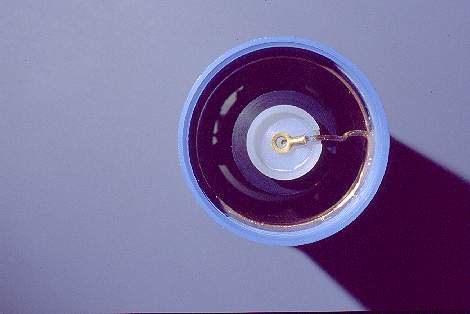
The inner assembly:
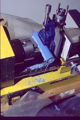
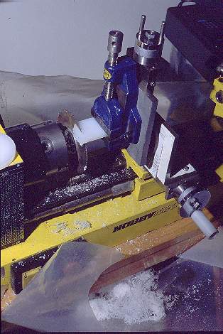 A hobby lathe
is a very versatile tool! Here it is shown configured for sawing a servo
mounting plate to the rough size. Later, the circular saw was replaced
by a cylindrical router bit, and then the precise finishing was performed.
Note that setting up a lathe in this way allows full milling functionality.
A hobby lathe
is a very versatile tool! Here it is shown configured for sawing a servo
mounting plate to the rough size. Later, the circular saw was replaced
by a cylindrical router bit, and then the precise finishing was performed.
Note that setting up a lathe in this way allows full milling functionality.
PA plastic generates lots of heat when frictioning against a tool. It
will easily melt, thus loosing precision and finish quality. To avoid this,
it's best to cool the tool with some liquid while working, but in my case,
using the lathe in my wooden-floored apartment, this isn't practical. The
solution is to work with very sharp tools at low speed.
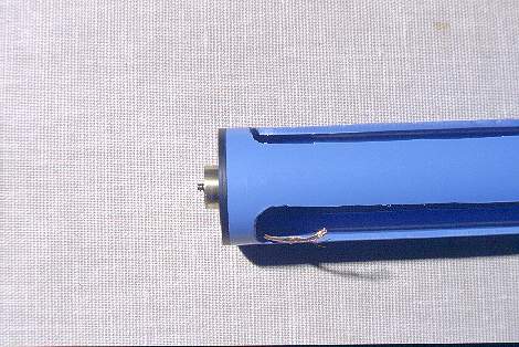
I did not buy plastic sheet stock for this project. Instead, I turned
my own plates from the same round 75mm PA stock used to make the base plate,
base cup and top cone.
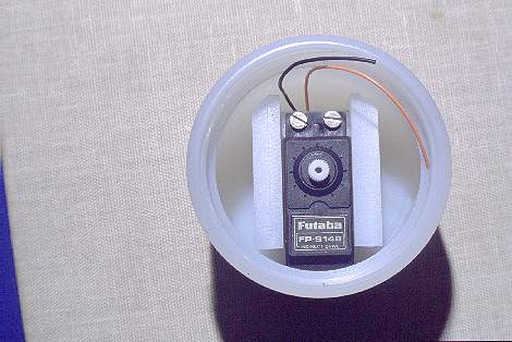 The two servo
mounting plates and the mounting block have been joined to the servo, and
test-fitted in the base cup. Note that one edge of each plate is chamfered.
This is necessary to be able to introduce the assembly into the cup, because
there is a rim, used to seat the coil tube, which has a narrower internal
diameter than the rest of the cup. The rear end of the servo is tucked
under this rim, so that its output shaft is precisely centered in the cup.
The two servo
mounting plates and the mounting block have been joined to the servo, and
test-fitted in the base cup. Note that one edge of each plate is chamfered.
This is necessary to be able to introduce the assembly into the cup, because
there is a rim, used to seat the coil tube, which has a narrower internal
diameter than the rest of the cup. The rear end of the servo is tucked
under this rim, so that its output shaft is precisely centered in the cup.
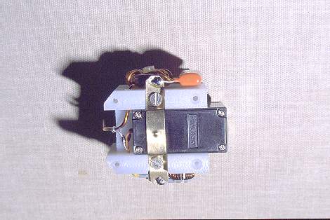
The servo is modified in three ways:
- The white output shaft internally carries a gear and a cam. This cam
originally is used to keep the shaft from rotating over more than three
quarters of a turn. This cam must be cut off, allowing continuous rotation.
- The rear end of the servo originally carries a mounting flange equal
to that at the front (top in this photo), with two screw holes. This rear
mounting flange would simply not fit inside the cup, and is cut off.
- The entire servo electronics, including the feedback potentiometer,
are removed. Instead, the decoupling components C2, C3 and FB1 are
installed inside.
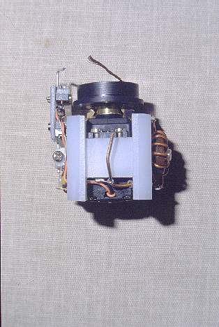 This picture
shows the servo assembly seen from the front (grounding) side. The servo
has been fitted with its wheel, the rotor base plate and slip ring. Also,
the contact springs and the entire limit switch and impedance matching
assemblies have been installed. This is the complete assembly that goes
into the base cup.
This picture
shows the servo assembly seen from the front (grounding) side. The servo
has been fitted with its wheel, the rotor base plate and slip ring. Also,
the contact springs and the entire limit switch and impedance matching
assemblies have been installed. This is the complete assembly that goes
into the base cup.
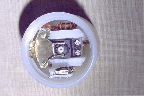
The limit switches are on the left side. They have the diodes D1 and
D2 installed between their pins. The top switch will later directly interface
to the bottom side of the limit rotor ring, while the bottom switch employs
a wire lever to engage to the limit rotor ring's top side.
On the right side is the toroidal inductor L2, and the coupling capacitor
C1. The ground connections of both sides are brought to the front via small
holes in the two servo mounting plates, and joined there. The heavy wire
pointing upwards is the ground connection. It will later be bent down,
and soldered to the solder lug attached to the cup threaded insert, as
the last step of building this antenna.
The live connections of both sides are soldered to the two ends of the
center contact spring.
The slip ring contact spring can be seen contacting the slip ring on
both sides, under the rotor base plate.
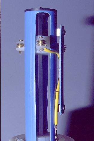
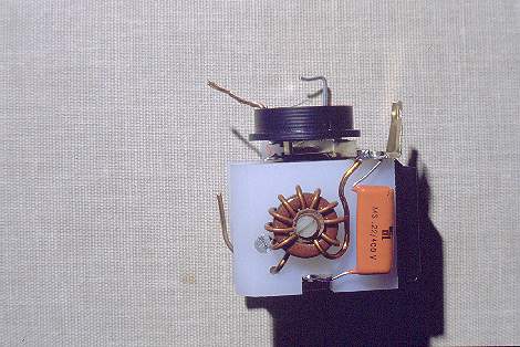 This side view shows
the RF portion of the circuit. RF energy from the center contact spring
is routed through a large capacitor to the contact spring on top, which
applies this RF to the base of the loading coil, to the movable tap via
the slip ring, and to the impedance matching coil that has its other end
grounded.
This side view shows
the RF portion of the circuit. RF energy from the center contact spring
is routed through a large capacitor to the contact spring on top, which
applies this RF to the base of the loading coil, to the movable tap via
the slip ring, and to the impedance matching coil that has its other end
grounded.
Note that in principle it's not necessary to use a 400 Volt capacitor
here, but I did it for safety reasons: Should I ever strike power lines
with this antenna, or even get a lightning hit, the combination of the
toroidal inductor to ground and this capacitor in series should protect
the radio to a very high degree.
The stranded wire protruding from the rotor base plate is soldered into
a hole in the slip ring, and will later be connected to the lowermost grooved
wheel, which doubles as the movable tap on the loading coil.
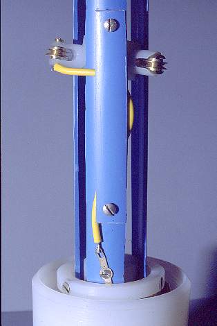
 The limit switch
side can be seen here. L3 and C4 are visible. The most interesting feature
is the steel wire and associated parts, used to link the lower limit switch
to the top surface of the limit rotor ring.
The limit switch
side can be seen here. L3 and C4 are visible. The most interesting feature
is the steel wire and associated parts, used to link the lower limit switch
to the top surface of the limit rotor ring.
 This is the bottom
view of the servo assembly. The center contact spring is featured prominently
here. It is screwed to the two servo mounting plates, and has a raised
contact point, that produces a sure one-spot contact to the center contact
button of the base.
This is the bottom
view of the servo assembly. The center contact spring is featured prominently
here. It is screwed to the two servo mounting plates, and has a raised
contact point, that produces a sure one-spot contact to the center contact
button of the base.
Note the four holes drilled into these plates. These are the ones that
take the screws which attach the assembly to the base cup. They are conically
enlarged, in order to facilitate assembly. Without these conical enlargements
it proved difficult to fit all four screws, given the unavoidable imprecisions
of home construction.
 The servo assembly
mounted inside the base cup. Note how everything fits precisely! There
is relatively little room wasted.
The servo assembly
mounted inside the base cup. Note how everything fits precisely! There
is relatively little room wasted.
When properly built, the assembly just barely can slip into and out
of the cup, without forcing anything.
Note how the fingers of the coil end contact spring are bent into a
rounded shape. This is needed for allowing the coil tube to be installed,
with these spring fingers sliding off and on the contact plate during assembly.
 The lathe is
configured as milling machine to make the slots in the slotted tube. A
simple core was made from PE before, in order to help support the tube.
Due to the softness of the PVC tube, the finish quality of this slotting
job was not very good, but this is of no consequence to the performance
of the system, as long as the chariot legs can slide freely.
The lathe is
configured as milling machine to make the slots in the slotted tube. A
simple core was made from PE before, in order to help support the tube.
Due to the softness of the PVC tube, the finish quality of this slotting
job was not very good, but this is of no consequence to the performance
of the system, as long as the chariot legs can slide freely.
These slots are 14mm wide, giving the chariot legs enough clearance
to avoid binding even if the chariot decenters because of some imprecision.
The slots run almost the full length of the tube, excepting only the areas
covered by the top and base plates of the rotor.
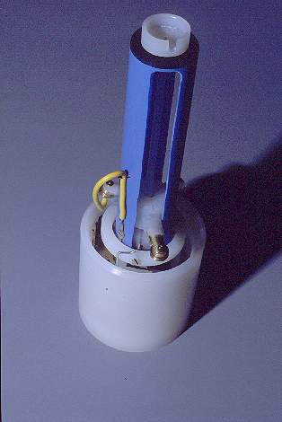
 This is the
bottom end of the rotor. The base plate has been pressure-fitted into the
tube, but it could also have been glued, or fixed with some screws. The
slip ring, its sliding surface finished using fine sandpaper and polishing
compound, was epoxied onto the servo wheel. This wheel is screwed to the
rotor base plate, using two tiny M2 bolts that will make their own threads
in the holes provided in the servo wheel.
This is the
bottom end of the rotor. The base plate has been pressure-fitted into the
tube, but it could also have been glued, or fixed with some screws. The
slip ring, its sliding surface finished using fine sandpaper and polishing
compound, was epoxied onto the servo wheel. This wheel is screwed to the
rotor base plate, using two tiny M2 bolts that will make their own threads
in the holes provided in the servo wheel.
The screw that holds the servo wheel to the servo must be inserted before
attaching the rotor base plate to the servo wheel. For mounting the wheel
on the servo, the screw head can be accessed through the hole that will
later take up the limit coupler axle.
The stranded wire runs through a slanted 1mm hole drilled into the rotor
base plate, and continues through a similar hole drilled straight into
the slip ring, where the contact is soldered before gluing the parts together.
 This picture
shows the same assembly from the front. Some solder residue can be seen.
This picture
shows the same assembly from the front. Some solder residue can be seen.
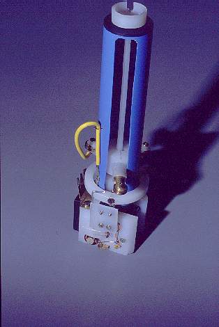 Here are the
complete innards of the antenna, from the centering cup on the top to the
servo assembly! You can see how the limit rotor ring activates the two
limit switches, and how the yellow wire connects the wire coming from the
slip ring to the lowermost grooved wheel. More about this wire later.
Here are the
complete innards of the antenna, from the centering cup on the top to the
servo assembly! You can see how the limit rotor ring activates the two
limit switches, and how the yellow wire connects the wire coming from the
slip ring to the lowermost grooved wheel. More about this wire later.
The limit coupler axle on this picture is the first one I made. It is
nylon, which proved to be a little too flexible for best performance. I
later replaced it by one made from durocotton, which is much stiffer. You
may ask why not making it from metal. The reason is that any long conductive
piece inside the coil would degrade the Q, lowering the antenna's efficiency!
Also there would be risk of arcing at the top of the axle. The entire reason
for placing the limit switches down in the base, and activating them with
these mechanical linkages made from plastic, is preserving the coil's high
Q!
To adjust the limit switch trip points, first the conical spring is
bent such that the limit rotor will rest in the center of its range. This
allows it to move 2mm in each direction. Then the lever of the upper limit
switch is bent to make it trip when pushing the limit rotor down. Finally,
the lower limit switch is adjusted by loosening the screw fixing the plastic
block to the coupler wire, and sliding the block to a suitable position
so that lifting the limit rotor will trigger the switch.
The chariot floats loosely inside the slotted tube. It has considerable
clearance, so it won't bind if there is some excentric motion because of
imprecisions. The wheel that pokes forward in this photo is the spring
loaded, telescoping one.
 After a few tests,
the simple yellow jumper wire showed to be insufficient. It bent away from
the correct shape, and caused friction by scraping against the coil. This
did not keep the antenna from working properly, but it slowed down the
tuning process and forced the mechanics. For that reason I conceived a
simple guide for the wire, made from a segment of PVC tube, which eliminated
this problem. It is mounted with two M3 screws self-threaded into the slotted
tube, and some junkbox spacers.
After a few tests,
the simple yellow jumper wire showed to be insufficient. It bent away from
the correct shape, and caused friction by scraping against the coil. This
did not keep the antenna from working properly, but it slowed down the
tuning process and forced the mechanics. For that reason I conceived a
simple guide for the wire, made from a segment of PVC tube, which eliminated
this problem. It is mounted with two M3 screws self-threaded into the slotted
tube, and some junkbox spacers.
Notice how the three legs are installed at different heights in the
chariot center piece. Since the coil pitch is 3mm, and the legs are 120
degrees apart from each other, the height difference between each leg and
the next is 1mm. When this is done correctly, the chariot will end up perfectly
leveled inside the coil.
 This frontal
view allows to see how the wire bends in this guide. It does not bind anywhere.
I did all the tests of the antenna using this yellow wire, which has a
finely stranded conductor, and thick, rubbery insulation. But in the end
I opted for replacing this wire by a piece of RG174 coax line, with the
braid and center conductor shorted. Thanks to the braid, this coax cable
has much greater torsional stiffness, without being much harder to bend.
This proved an advantage in this application.
This frontal
view allows to see how the wire bends in this guide. It does not bind anywhere.
I did all the tests of the antenna using this yellow wire, which has a
finely stranded conductor, and thick, rubbery insulation. But in the end
I opted for replacing this wire by a piece of RG174 coax line, with the
braid and center conductor shorted. Thanks to the braid, this coax cable
has much greater torsional stiffness, without being much harder to bend.
This proved an advantage in this application.
Also the direct connection to the headed axle was used only for the
tests. It would break in the long run, since the wire would be flexing
here! Before final assembly of the antenna, I looped the coax a half turn
around the chariot leg, soldered it on the top side, and wound a few loops
of magnet wire around, which I then secured with epoxy glue. I expect this
to last for a long time.
 Here's the complete
assembly (except for the wire guide) installed in the base cup.
Here's the complete
assembly (except for the wire guide) installed in the base cup.
 The loading
coil assembly has been installed. This was done only for the photo, which
shows how the top end of the coil runs through the slot in the centering
cup.
The loading
coil assembly has been installed. This was done only for the photo, which
shows how the top end of the coil runs through the slot in the centering
cup.
Final assembly of the unit starts with the coil tube removed from the
base cup. It requires first screwing the top cone into the coil tube, sealing
the thread with silicone caulk. The drilled and tapped stainless steel
bolt is screwed into the top cone, also sealing it with silicone. Then,
using a long screwdriver, the M3 stainless steel bolt that connects the
top of the coil can be inserted through the coil. This screw is sealed
with low or medium strength Loctite thread locker.
Holding vertically the base cup with installed innards, the loading
coil with the top parts is lowered onto it. The telescoping chariot leg
is compressed, and the chariot inserted into the coil tube. Then the coil
is gently rotated, while manually guiding the grooved wheels, one after
another, uppermost first, so they will climb onto the start of the coil
wire, in the proper sequence. When this has happened, the coil tube's lower
thread is engaged with the base cup, and screwed down a few turns. But
before the centering cup at the top jams (it will rarely be perfectly
centered during assembly), you need to apply a trick I came up with: Connect
a 6 Volt power supply to the unit! The servo will run, the chariot will
screw itself up the coil, and any imprecise centering of the centering
cup will transform into an orbiting motion. While the servo runs, SLOWLY
finish screwing down the coil tube. The centering cup will cleanly latch
its notch on the end of the coil wire, and then cleanly engage in the circular
groove in the top cone! It's incredibly easy to do, once one has figured
out the trick of doing it with running motor! Before that, I was close
to pulling my last hairs out!
Leave this thread without silicone caulk, until you have completed all
testing. Once the antenna has been found to work perfectly, open it a last
time and reassemble with some silicone caulk in this thread.
Previous page
Next page