|
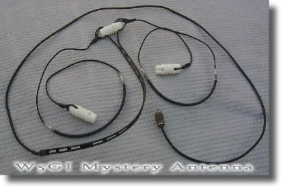
Antena W5GI MULTIBANDA 6 - 80 Mts. |
||||||||||||||||||||||||||||||||||||||||||||||||||||||||||||||||||||||||||||||||||||||||||
|
|
||||||||||||||||||||||||||||||||||||||||||||||||||||||||||||||||||||||||||||||||||||||||||
|
|
||||||||||||||||||||||||||||||||||||||||||||||||||||||||||||||||||||||||||||||||||||||||||
|
|
||||||||||||||||||||||||||||||||||||||||||||||||||||||||||||||||||||||||||||||||||||||||||
|
A multi-band
wire antenna that performs exceptionally
well even though it confounds antenna
modeling software
Click
FAQ
to read a list of frequently asked questions
and answers about the W5GI Mystery Antenna.
The
design of the Mystery antenna was inspired
by an article written by James E. Taylor,
W2OZH, in which he described a low profile
collinear coaxial array. This antenna covers
80 to 6 meters with low feed point impedance
and will work with most radios, with or
without an antenna tuner. It is
approximately 100 feet long, can handle the
legal limit, and is easy and inexpensive to
build. It’s similar to a G5RV but a
much better performer especially on 20
meters.
The W5GI
Mystery antenna, erected at various heights
and configurations, is currently being used
by thousands of amateurs throughout the
world. Feedback from users indicates
that the antenna has met or exceeded all
performance criteria. The “mystery” part of
the antenna comes from the fact that it is
difficult, if not impossible, to model and
explain why the antenna works as well as it
does. The antenna is especially
well suited to hams who are unable to erect
towers and rotating arrays. All
that's needed is two vertical supports (trees
work well) about 130 feet apart to permit
installation of wire antennas at about 25
feet above ground.
The W5GI Multi-band Mystery Antenna is a
fundamentally a collinear antenna comprising
three half waves in-phase on 20
meters with a half-wave 20 meter line
transformer. It may sound and look like a
G5RV but it is a substantially different
antenna on 20 meters. Louis Varney’s
antenna, although three half waves long, was
an out-of-phase aerial. Mr. Varney had
two specific reasons for selecting a 3 half
waves on 20... he wanted a four-lobe
radiation pattern, at least unity gain and a
low feed point impedance.
The Mystery
antenna, on the other hand, presents a
six-lobe pattern on 20 meters, gain
broadside to the antenna, and also low feed
point impedance to simplify matching the
antenna to the rig. Additionally,
the Mystery antenna is designed to work at
least as well, on the other HF bands as a
G5RV. In short, the Mystery antenna is
a sky wire that incorporates the advantages
of a 3 element collinear and the G5RV
antenna.
In its
standard configuration, a collinear antenna
uses phase reversing stubs added at the ends
of a center fed dipole. These stubs put the
instantaneous RF current in the end elements
in phase with that in the center element.
You can make these phase reversing stubs
from open wire line or coaxial cable.
Normally, a shorted quarter-wave stub is
used, but an open-ended half wave stub would
also work. The problem is that the dangling
stubs are unwieldy and or unsightly.
An article
written by James E. Taylor, “COCOA-A
Collinear Coaxial Array,” published in
73 Amateur Radio, August 1989, describes a
low profile collinear coaxial array. According
to Taylor, when you apply a RF voltage to
the center conductor at the open end, the
stub causes a voltage phase lag of 180
degrees at the adjacent coax shield. This
happens because the RF is delayed by one
quarter-cycle as it passes from left to
right, inside the coax to the shorted (opposite)
end. There’s another quarter-cycle delay as
the wave passes back from right to left
inside the coax and emerges on the shield at
the open end. Add up the delays and you get
a total time delay of one-half cycle, or 180
degrees. In essence, the coax section serves
two purposes: it provides the necessary
delay and provides part of the radiating
element in a collinear array.
The first
prototypes of the Mystery antenna used the
Taylor formulas, which which called for
cutting the wires to a quarter wave length
using the formula 234/f(Mhz) and the
coax, using the same formula, but applying
an appropriate velocity factor. The first
version of my antenna worked well on 20
meters but failed as a multi-band antenna.
The second
antenna was built with constructed with the
coax cut to the same length as the wire.
This was done with the belief that perhaps
the coax didn’t behave like coax and
therefore the velocity factor wasn’t
applicable. Surprisingly, the new
antenna performed exceptionally well on 20
meters, had low SWR and performed just as
well on the other HF bands and 6 meters as
my G5RV reference antenna.
Step-by-Step
Construction
Builders of the Mystery
antenna will need the following materials:
3 wish bone insulators
About 70 feet of wire (14
gauge household electrical wire works well,)
Sufficient twin lead or
open wire to make a half wave section on 20
meters. Window-type 18 gauge 300 ohm ribbon
works bes
34 feet of RG8X mini-coax
An electrical connector,
available from most electrical parts stores,
to connect the twin lead and coax
Shrink tubing to cover the
exposed coax joints
The antenna can be built in
less than an hour when you have the above
materials. When you’re ready to proceed,
perform the following steps:
Cut the electrical wire
into four equal lengths of 17 feet.
Cut the two lengths of coax
to 16’6” each.
Cut a 20 meter half-wave
section of twin lead. This piece needs
to be adjusted by its velocity factor.
If 300 ohm window type line is used with a
VF of .91, the total length will be 30 ft.
Alternatively, 450 ohm, solid 300 ohm or
homemade open-wire line can be used provided
the electrical length is on-half wave on 20
meters. Actual length will vary,
typically between 27 and 35 ft., depending
on type and velocity factor.
Trim two inches of braid
from one end of both lengths of coax (Item
A).
Trim one inch of braid and
center insulator from the opposite end of
both coax sections (Item B).
Build a 20-meter dipole without end
insulators. Note: The next
two steps 7 and 8 of the construction
process involve connecting only the "inner"
end section of the coax section to one end
of the dipole; the shield is not connected
to anything here. At the other end of
the coax section both the coax shield and
second wire section are connected to the
coax center conductor. Connect the
opposite end of the coax (Item B) to braid
AND quarter wave wire section, cover with
shrink tubing, and connect to end insulator
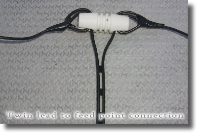
as shown in Photo C below. Install the
twin lead through the holes of the center
insulator (you may have to enlarge the holes)
and solder to antenna wire as shown in
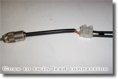
photo D below. Connect the
opposite side of the twin lead to the coax
as shown in
photo E below. Almost any type of
connection will work provided the connection
is stable and sealed properly.
Install the antenna with
the center conductor at least 25 feet high.
Mine is installed in a horizontal plane;
however, others have installed the ‘GI
antenna as an inverted-vee and are getting
excellent results.
On-the-Air
Performance
On 20 meters,
you should expect 3-6 dB gain over a dipole
and a 6-lobe radiation pattern with an
elongated figure 8 pattern perpendicular to
the plane of the antenna. This is typical of
a 3 element collinear array. For a
simple explanation of collinear arrays read
"Troubleshooting Antennas and Feed lines" by
Ralph Tyrrell, W1TF. On all other
bands the antenna performs like a G5RV,
which is really a random length dipole on
all but 20 meters. M. Walter Maxwell, in "Reflections
II, Transmission Lines and Antennas",
aptly describes this phenomenon. Several
users report it is possible to use the
antenna on 160 meters but you will need to
connect the twin lead together at the point
where it connects to the coax. On 160, the
antenna performs like a Marconi. Those who
have used the antenna on 160 say the “GI
Mystery” antenna is a quieter receiving
aerial compared to other 160-meter antennas.
As for the
theory of operation, it remains a mystery.
At least three “experts” tried computer
modeling the antenna. All three rendered
completely different findings.
Notes:
(1) Information on this page has been taken
from an article published in the July, 2003
issue of CQ magazine. You can download
a copy of the article in Adobe Acrobat
format by clicking
HERE. (2) W5GI will
build an antenna for a nominal fee. Discount
prices start at $65.00, plus shipping, for
the W5Gi multi-bander. Mono band antennas
cost more because a 4:1 balun is used. (3) For
additional information, or to order an
antenna, please call or send an mail.
(4) Dimensions for the mono-band antenna:
BAND
Inside wire
Coax
Outside wire
Overall length
10.1
23' 10"
23' 4"
23' 6"
141 ft 4 inches
14.18
17' 2"
16' 8"
16' 10"
101 ft 4 inches
18.13
13' 7"
13' 1"
13' 3"
79 ft 10 inches
21.25
11' 9"
11' 3"
11' 5"
68 ft 10 inches
24.9
10' 1"
9' 7"
9' 9"
58 ft 10 inches
28.5
8' 11"
8' 5"
8' 7"
51 ft 10 inches
50.125
7' 10 "
7' 4"
7' 6"
45 ft 4 inches
The above dimensions are for a dipole hung
in the horizontal plane. They were
calculated by using the formula 234/freq (MHz)
plus additional length for attaching to
connectors/insulators. If the antenna is to be installed an
Inverted V, increase all lengths by 5%. Any of the above
antennas can easily be used as multi band
antennas by eliminating the 4:1 balun
and using open wire/twin
lead directly to an antenna tuner
(4) Dimensions for the
multi-band antenna:
Inside wire
Coax
Outside wire
Overall length
17' 2"
16' 8"
16' 10"
101 ft 4"
This antenna uses a twin lead matching stub
instead of a 4:1 balun.
Use only 300 ribbon line for the matching
stub. Start with 34 ft 7", trim as
necessary to obtain lowest SWR.
Mono-banders with either a voltage or
current (preferred) 4:1 balun.
This | ||||||||||||||||||||||||||||||||||||||||||||||||||||||||||||||||||||||||||||||||||||||||||