 This is how
the completed base looks, when mounted on the car roof. Sorry, I did not
wash the car before installing the antenna!
This is how
the completed base looks, when mounted on the car roof. Sorry, I did not
wash the car before installing the antenna!
 I have
heard experienced mechanics say that it is difficult to make threads with
a lathe. Expecting trouble, I was soon surprised that even my very first
thread was perfectly usable! This photo shows a piece of brass stock in
my lathe, just after finishing the external thread of the insert that goes
in the mounting base.
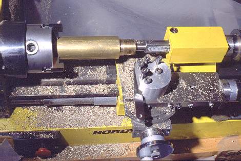
I have
heard experienced mechanics say that it is difficult to make threads with
a lathe. Expecting trouble, I was soon surprised that even my very first
thread was perfectly usable! This photo shows a piece of brass stock in
my lathe, just after finishing the external thread of the insert that goes
in the mounting base.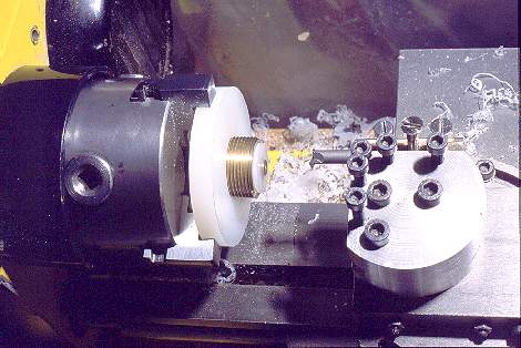 Here
the entire base has been assembled, while still mounted in the lathe, to
test the fit of the plastic threads. Cutting precise threads in plastic
is a little harder than in brass, because the soft material tends to flex
away from the tool, so it's necessary to cut a little deeper to compensate.
Frequent test fitting during the process avoids overcutting.
Here
the entire base has been assembled, while still mounted in the lathe, to
test the fit of the plastic threads. Cutting precise threads in plastic
is a little harder than in brass, because the soft material tends to flex
away from the tool, so it's necessary to cut a little deeper to compensate.
Frequent test fitting during the process avoids overcutting.
The tool used to cut inner threads can be seen here. It needs to be
very sharp for proper finish quality in plastic.
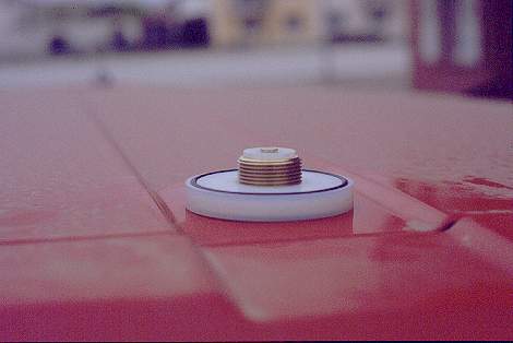
This is how
the completed base looks, when mounted on the car roof. Sorry, I did not
wash the car before installing the antenna!
Note how the O-ring extends slightly above the surface of the base plate.
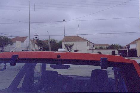 When the antenna
is dismounted, a simple cap is screwed onto the base, in order to protect
the contacts from dirt, water and corrosion. This is how the car roof looks
with dismounted antenna. Only the quarter wave whip for VHF remains in
place at all times, since it fits easily into most garages. The other wires
in this photo are power and phone lines in the background!
When the antenna
is dismounted, a simple cap is screwed onto the base, in order to protect
the contacts from dirt, water and corrosion. This is how the car roof looks
with dismounted antenna. Only the quarter wave whip for VHF remains in
place at all times, since it fits easily into most garages. The other wires
in this photo are power and phone lines in the background!
 The base cup is
made from solid PA, and requires removing a lot of material from the inside.
Those who have access to a large lathe and large drill bits will be able
to do this very quickly, but for me it meant removing almost all the material
in successive passes of small tools.
The base cup is
made from solid PA, and requires removing a lot of material from the inside.
Those who have access to a large lathe and large drill bits will be able
to do this very quickly, but for me it meant removing almost all the material
in successive passes of small tools.
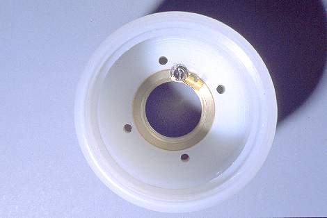
A threaded insert, larger than that of the base but otherwise similar, is screwed into the cup. It takes an M3 bolt that serves a double purpose: It holds a solder lug providing ground connection to the antenna innards, while also locking the threaded insert in place, so it won't unscrew from the cup when installing or removing the antenna from its base.
Note that the four holes used for the bolts that hold the servo mounting plates are NOT in a square arrangement, but a rectangular one. These holes can be drilled using a drill stand, or using the lathe configured as milling machine. They must be drilled in the proper locations, so that later the contact spring for the coil end properly rests on the coil contact plate.
Likewise, the threaded hole in the brass insert must be drilled in the
proper location, so that the solder lug will be roughly centered under
the end of the servo, when the insert is correctly screwed into the cup.